background image

12

How to Assemble the Blades and Light Kit (continued)

Light Plate

Assembly

Socket Plate

Assembly

Socket Plate

Assembly

Housing Ring

Assembly

100-WATT

Minican

Light Bulb (1)

Figure 4

Figure 5

Figure 6

Figure 7

Housing Ring

Assembly

Screws (3)

Trim

Screws (3)

Trim

Screws (3)

Glass

Assembly

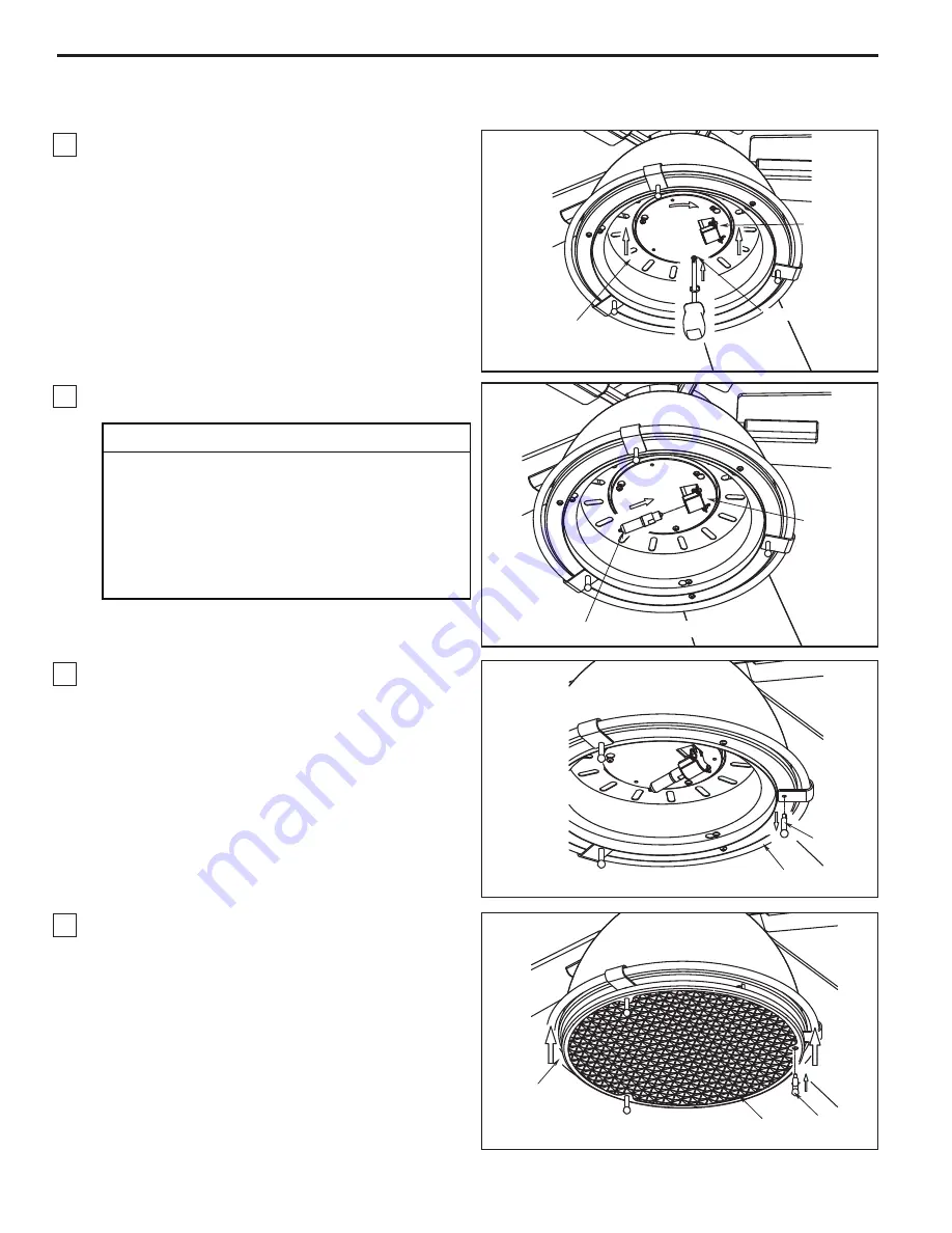
4.

Remove one of the three screws in the light plate

assembly. Slightly loosen the remaining two screws. 

Assemble the socket plate assembly to the light plate

assembly using the two key slots. Replace the third

screw and securely tighten all three screws 

(Figure 4).

5.

Insert light bulb into socket (Figure 5).

6.

Remove the three trim screws of support bracket

from the housing ring assembly. Retain the

screws for reinstallation in next step (Figure 6).

7.

Assemble the glass assembly to the housing ring 

assembly using the previous trim screws (Figure 7). 

CAUTION

To reduce the risk of fire, use 100-watt max. type 

T4-minican JD E11 tungsten halogen bulb. Turn off 

the wall switch and allow the bulb to cool for 10 

minutes before relamping.

Bulb is pressurized and may shatter. DO NOT 

TOUCH BULB WITH BARE HANDS. Fingerprints 

may result in shorter bulb life. Remove fingerprints

with alcohol prior to use.

Summary of Contents for Breckenfield FP7951

Page 1: ...OWNER S MANUAL READ AND SAVE THESE INSTRUCTIONS Model No FP7951 Net Weight 14kg 30 86 lbs The Breckenfield Ceiling Fan...

Page 2: ...l disconnecting means to prevent power from being switched on accidentally When the service disconnecting means cannot be locked securely fasten a warning device such as a tag to the service panel 3 B...

Page 3: ...to Assemble Your Ceiling Fan 6 How to Hang Your Ceiling Fan 8 How to Wire Your Ceiling Fan 9 0 1 g n i s u o H y p o n a C e h t g n i l l a t s n I How to assemble the Blades and Light kit 11 How to...

Page 4: ...ed with this product and or any accessories designated specifically for use with this product by Fanimation Substitution of parts or accessories not designated for use with this product by Fanimation...

Page 5: ...rooms If the room is unoccupied turn off the ceiling fan to save energy Using the Ceiling Fan Year Round Summer Season Use the ceiling fan in the counter clockwise direction The airflow produced by th...

Page 6: ...n the two set screws and locking nuts in the downrod support Figure 4 Pin Hanger Ball Set Screw Downrod Fan Motor Assembly Screw 3 Support Bracket Light Plate Assembly Figure 5 5 Remove one of the thr...

Page 7: ...7 Route wires through motor coupling cover canopy screw cover and canopy Figure 7 8 Reinstall the hanger ball on the downrod as follows Route the three 80 inch wires through the hanger ball Position...

Page 8: ...shers supplied with the outlet box Figure 2 NOTE Outlet box screws pass through slotted holes of the hanger bracket Figure 2 2 Pull the electric wires in the outlet box down through the opening in the...

Page 9: ...ge the combination code in your transmitter and receiver 1 To set the transmitter code remove battery cover by pressing firmly below arrow and sliding cover off Slide code switches to your choice of u...

Page 10: ...d be spread apart with the grounded conductor and the equipment grounding conductor on one side of the outlet box and the ungrounded conductor on the other side of the outlet box Figure 6 Figure 6 BLA...

Page 11: ...de Blade holder Figure 2 Figure 3 HARDWARE USED x 10 1 4 20 x 14 mm SCREWS Motor Assembly 1 4 20 x 14 mm SCREWS 2 per assembly Blade Holder Socket Plate Assembly Socket Plate Single Pin Connector Moto...

Page 12: ...third screw and securely tighten all three screws Figure 4 5 Insert light bulb into socket Figure 5 6 Remove the three trim screws of support bracket from the housing ring assembly Retain the screws...

Page 13: ...es buttons for high medium and low fan speeds as well as buttons for fan off and light on off Infinite light levels are available by holding the light on off button Figure 3 Check to see that all conn...

Page 14: ...ning agents are not required and should be avoided to prevent damage to finish Do not use water when cleaning your ceiling fan It could damage the motor or the finish and create the possibility of ele...

Page 15: ...sing CAUTION Make sure main power is turned off 5 Tighten screws securely 1 Blades not attached to fan 2 Loose screws in motor housing 3 Screws securing fan blade holders to motor flywheel are loose 4...

Page 16: ...0 AP795109 AP795114 Blade Set 11 AP795105 Hand Held Remote 12 TR24WH RECAN54 Receiver Unit 13 HDWFP7951 16 14 Washer Head Screw 3 16 24x7 5 mm 16 4 Phillips Head Screw driver Screw 1 4 20x14 mm w Lock...

Page 17: ...el FP7951 Exploded View 1 3 4 2 7 10 NOTE The illustration shown is not to scale or its actual con guration may vary Product parts are subject to change without notice Figure 1 8 11 12 13 14 16 9 The...

Page 18: ......

Page 19: ...Copyright 2012 Fanimation 2012 05 V 01 10983 Bennett Parkway Zionsville IN 46077 888 567 2055 FAX 866 482 5215 Outside U S call 317 733 4113 Visit Our Website www fanimation com...

Page 20: ...Ventilador de techo Modelo N FP7951 MANUAL DEL PROPIETARIO LEA Y GUARDE ESTAS INSTRUCCIONES The Breckenfield Peso neto 14 kg 30 86 lbs...

Page 21: ...se de que la electricidad est desconectada en la caja de fusibles antes de realizar 1 la instalaci n el ctrica y no haga funcionar el ventilador sin las aspas Todos los procedimientos de conexi n el c...

Page 22: ...mo realizar la instalaci n el ctrica del ventilador de techo 28 29 23 24 24 25 27 Instalaci n de la cubierta del capuch n C mo ensamblar el ventilador de techo C mo utilizar su ventilador de techo Man...

Page 23: ...rar de completar todos los pasos y podr saber desde d nde retomar si fuera interrumpido NOTA Si no est seguro de la descripci n de una pieza consulte la ilustraci n del despiece 1 Veri que que haya re...

Page 24: ...ventilador de techo a velocidad baja y en el sentido de las agujas del reloj Esto produce una suave corriente ascendente que obliga al aire c lido que se acumula cerca del techo a bajar al espacio oc...

Page 25: ...n y las tuercas de seguridad en el soporte de la varilla interior Figura 4 Ranura de la bola colgante Pasador Tornillo de fijaci n Bola para colgar Tornillo 3 abrazadera de soporte Ensamble de la pla...

Page 26: ...8 Vuelva a colocar la semiesfera en el barral como se indica a continuaci n Pase los tres cables de 2 03 m 80 a trav s de la semiesfera Pase el pasador a trav s de los dos orificios en el barral y al...

Page 27: ...la caja de distribuci n el ctrica Pesta a Unidad del barral de la semiesfera ADVERTENCIA Si la pesta a no est en la ranura podr an producirse da os en los cables el ctricos y posibles descargas el ct...

Page 28: ...ndo el conector de cables suministrado Conecte el cable blanco desde la unidad del receptor marcado AC IN N al cable blanco de suministro de electricidad utilizando el conector de cables suministrado...

Page 29: ...tilador hasta que las aspas est n instaladas Podr a ocasionar ruidos y da os al motor ADVERTENCIA x 6 Aditamentos utilizados Conectores de cable Instalaci n de la cubierta del capuch n 2 Coloque y aju...

Page 30: ...te del motor mediante los tornillos de 1 4 20 x 14 mm a trav s de los orificios ubicados al costado del soporte del motor Figura 2 soportes de las aspas y vuelva a ajustarlas si fuese necesario x 10 A...

Page 31: ...ra 7 C mo ensamblar los Blades y kit de luz cont 4 Extraiga uno de los tres tornillos de la unidad de la placa Afloje levemente los otros dos tornillos Instale la placa de conexi n en la unidad de la...

Page 32: ...cable pelado en los conectores de cables con la excepci n del cable de toma de tierra No utilice el ventilador hasta que las palas est n colocadas en su lugar ya que de lo contrario se podr a causar r...

Page 33: ...antenimiento 1 El nico mantenimiento necesario para el ventilador de techo es una limpieza peri dica Al llevar a cabo la limpieza use s lo un cepillo suave o un pa o sin pelusas para evitar rayar el a...

Page 34: ...erior de la caja del interruptor PRECAUCI N Aseg rese de que el suministro principal de electricidad est desconectado 5 Ajuste bien los tornillos 3 EL VENTILADOR OSCILA EN EXCESO 1 El tornillo de fija...

Page 35: ...techo Cubierta de uni n del motor Bolsa de accesorios conectores de los cables 4 arandela de la cabeza del tornillo DE 3 16 24 x7 5 mm Arandela de fibr de 3 16 16 tornillo de cabeza troncoc nica de 1...

Page 36: ...36 6 5 15 Modelo FP7951 Despiece 1 3 4 2 7 10 Figura 1 8 11 12 13 14 16 9 NOTA The Breckenfield...

Page 37: ......

Page 38: ...12 Fanimation 2012 05 V 01 10983 Bennett Parkway Zionsville IN 46077 Llame sin cargo al 888 567 2055 FAX 866 482 5215 Desde fuera de los EE UU llame al 317 733 4113 Visite nuestro sitio Web en www fan...

Reviews: