background image

7

How to Wire Your Ceiling Fan

If you feel that you do not have enough electrical wiring knowledge or experience, have your fan installed by a 

licensed electrician. 

1.

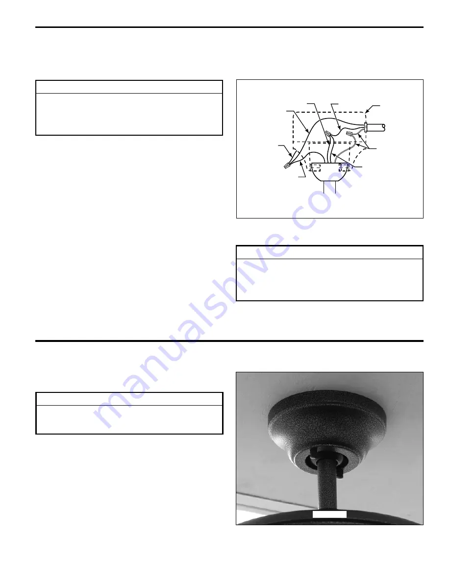
 Connect the green grounding lead from the hanger ball 

and the green grounding lead from the hanger bracket to 
the supply grounding conductor (this may be a bare wire 
or wire with green colored insulation). Securely connect 
wires with wire connectors supplied.

2.

 Securely connect the white fan motor wire to the white 

supply (neutral) wire using wire connector supplied. 


Securely connect the black fan motor wire and blue wire 
to the black supply wire using wire connector supplied 
(Figure 1). After connections have been made, turn leads 
upward and carefully push leads into the outlet box, with 
the white and green leads on one side of the outlet box 
and the black and blue leads on the other side of the outlet 
box.

3.

 Proceed to the next step of “Installing the Canopy 

Housing“.

Household

Supply

Listed

Outlet Box

Black

Green Wire

(Ground) from

Hanger Bracket

Green Wire

(Ground)

Black

Fan Wire

White

Blue

Green Wire

(Ground) from

Hanger Bowl

Figure 1

WARNING

To avoid possible electrical shock, be sure electricity is 

turned off at the main fuse box before wiring.

NOTE: If you are not sure if the outlet box is grounded, 

contact a licensed electrician for advice, as it must be 

grounded for safe operation.

WARNING

Check to see that all connections are tight, including 

ground, and that no bare wire is visible at the wire 

connectors, except for the ground wire.  Do not operate 

fan until the blades are in place.  Noise and motor 

damage could result.

Installing the Canopy Housing

Figure 1

NOTE:


 This step is applicable 

after

 the necessary wiring 

is completed. 

WARNING

To avoid possible fire or shock, make sure that the 

electrical wires are completely inside the canopy housing 

and not pinched between the housing and the ceiling.

1.

 Screw in two threaded rods into the Hanger Bracket 

(Figure 1).

NOTE:


 The threaded rods in the hanger bracket serves as 

guides for easier installation.

2.

 Securely attach the Canopy Housing to the Hanger 

Bracket using the external lockwashers and knurled knobs 
supplied with your fan (Figure 1).

Summary of Contents for Edgewood TF900 Series

Page 1: ...OWNER S MANUAL READ AND SAVE THESE INSTRUCTIONS Model No TF900 The Edgewood Wet Location Ceiling Fan Net Weight 8 16 kg 18 0 lbs ...

Page 2: ...ecial legal rights and you may also have other rights that vary from state to state 10 A certain amount of wobble is normal and should not be considered a problem or a defect LIMITED LIFETIME WARRANTY Extends to the original purchaser of a Fanimation Fan Important Safety Instructions WARNING To avoid fire shock and serious personal injury follow these instructions 1 Read your owner s manual and sa...

Page 3: ...blade screwdriver One wire stripper Four wire connectors supplied WARNING Do not install or use fan if any part is damaged or missing This product is designed to use only those parts supplied with this product and or any accessories designated specifically for use with this product by Fanimation Substitution of parts or accessories not designated for use with this product by Fanimation could resul...

Page 4: ...ommonly used for support of light fixtures are not acceptable for fan support and may need to be replaced Consult a qualified electrician if in doubt Energy Efficient Use of Ceiling Fans Ceiling fan performance and energy savings rely heavily on the proper installation and use of the ceiling fan Here are a few tips to ensure efficient product performance Choosing the Appropriate Mounting Location ...

Page 5: ...oute wires through Motor Coupling Cover and Canopy Position Canopy on fan shown with open side facing up Figure 3 7 Reinstall the Hanger Ball Figure 3 on the Down rod as follows Route the three 80 wires through the Hanger Ball Position the Pin through the two holes in the Down rod and align the Hanger Ball so the Pin is captured in the groove in the top of the Hanger Ball Pull the Hanger Ball up t...

Page 6: ...ag bolt and flat washer attach safety cable to ceiling joist or wood structural member The lag bolt will pass through the flat washer safety cable loop the junction box and into the building structure Figure 2 You will first drill a pilot hole into the building structure to prevent splitting or cracking 2 Securely attach the hanger bracket to ceiling junction box acceptable for ceiling support Use...

Page 7: ...en Wire Ground from Hanger Bracket Green Wire Ground Black Fan Wire White Blue Green Wire Ground from Hanger Bowl Figure 1 WARNING To avoid possible electrical shock be sure electricity is turned off at the main fuse box before wiring NOTE If you are not sure if the outlet box is grounded contact a licensed electrician for advice as it must be grounded for safe operation WARNING Check to see that ...

Page 8: ... using the Screws w Lock washers as shown in Figure 2 5 Make sure the screws with lock washers securing the Blade Holders to the Motor Hub are tight and that the Blade Holders are properly seated Figure 2 NOTE Periodically check Blade Holder hardware and re secure if necessary see Maintenance Figure 2 8 INSTALLATION NOTE Do not connect fan blades until the fan is completely installed Installing th...

Page 9: ...lly check that the blade holders to motor hub screws are secure and tight Operating Instructions Pull Chain 1 Restore electrical power to the outlet box by turning the electricity on at the main fuse box 2 Check the operation of the fan by gently pulling on the pull chain switch Figure 1 3 If airflow is desired in the opposite direction turn the fan off and wait for the blades to stop turning Then...

Page 10: ...Clevis Pin 2d Bridge Pin 3 Ceiling Canopy P30030 4 Motor Coupling Cover AP30050 5 Fan Motor Assembly MATF900 6 Blade Holders Set of 5 AP30005 7 Blades Set of 5 AP90005 8 Hardware Bag Containing HDWTF900 5 32 Threaded Rods 2 HDWHW900 5 32 External Lockwashers 2 Knurled Knobs 2 Balance Kit BALKT Wire Connectors 4 Chain Coupler Chain Fob 8 32 x Junction Box Screws Stainless Steel 2 Support Cable Bag ...

Page 11: ...11 NOTE The illustration shown is not to scale or its actual configuration may vary TF900 Wet Location Fan Exploded View Figure 1 2a 2b 2c 2d 2 3 4 5 6 1 7 8 ...

Page 12: ...d state controls are not recommended choose an alternative control method 6 Tighten screws securely 3 FAN WOBBLES EXCESSIVELY 1 Setscrew and nut in downrod support is loose 2 Setscrew in downrod hanger ball assembly is loose 3 Screws securing fan blade holders to motor hub are loose 4 Blade holders not seated properly 5 Hanger bracket and or ceiling outlet box is not securely fastened 6 Fan blades...

Page 13: ......

Page 14: ...Copyright 2007 Fanimation 2007 06 10983 Bennett Parkway Zionsville IN 46077 888 567 2055 FAX 866 482 5215 Outside U S call 317 733 4113 Visit Our Website www fanimation com ...

Reviews: