background image

6

To avoid possible fire or shock, be sure electricity is
turned off at the main fuse box before hanging.

WARNING

6.

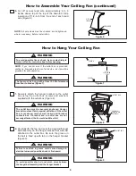
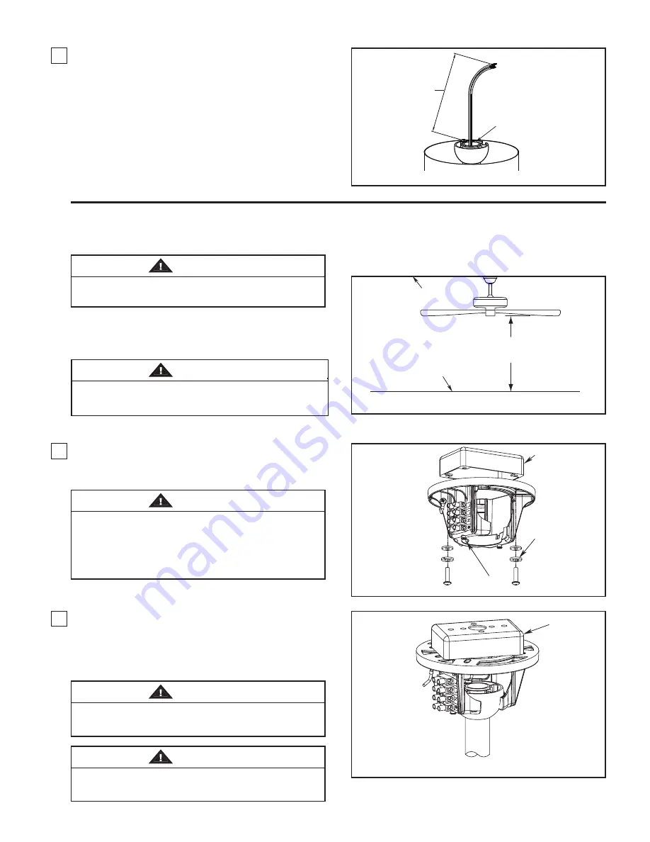
Cut  off  excess  lead  wire  approximately  6  to  9

inches  above  top  of  the  top  of  the  downrod.  Strip

insulation  off  1/2-inch  from  the  end  of  each  lead

wire (Figure 6).

1.

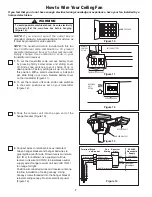
Securely  attach  the  hanger  bracket  to  the  outlet

box  using  the  outlet  box  screws  and  washers

supplied with the outlet box (Figure 8).

Figure 7

Figure 8

How to Assemble Your Ceiling Fan (continued)

How to Hang Your Ceiling Fan

NOTE:

If  you  are  not  sure  if  the  outlet  box  is  grounded,

contact  a  licensed  electrician  for  advise,  as  it  must  be

grounded for safe operation.

NOTE:

All set screws must be checked, and retightened

where necessary, before installation.

The  outlet  box  must  be  securely  anchored.  Hanger
bracket must seat firmly against outlet box. If the outlet
box  is  recessed,  remove  wall  board  until  bracket
contacts  box.  If  bracket  and  /or  outlet  box  are  not
securely attached, the fan could wobble or fall.

WARNING

2.

Carefully  lift  the  fan  and  seat  the  downrod/hanger

ball assembly on the hanger bracket that was just

attached  to  the  outlet  box.  Be  sure  the  groove  in

the ball is lined up with tab on the hanger bracket

(Figure 9).

Figure 9

Failure  to  seat  tab  in  groove  could  cause  damage  to
electrical wires and possible shock or fire hazard.

WARNING

To  avoid  possible  shock,  do  not  pinch  wires  between
the hanger ball assembly and the hanger bracket.

WARNING

DOWNROD

6 TO 9

INCHES

Figure 6

NO

LESS THAN

  2.3M

FLOOR

CEILING

The  fan  must  be  hung  with  at  least 2.3 M of clearance 
from floor to blades (Figure 7).

WARNING

OUTLET BOX

SCREW (2)

(Supplied with

Outlet Box)

TAB

OUTLET BOX

Summary of Contents for FP8000-220 The Akira

Page 1: ...Model No FP8000 220 OWNER S MANUAL READ AND SAVE THESE INSTRUCTIONS The Akira Ceiling Fan Finishes OB and PW Net Weight 10 1 kg 22 2 lbs ...

Page 2: ...RANTY Extends to the original purchaser of a Fanimation Fan Important Safety Instructions WARNING To avoid fire shock and serious personal injury follow these instructions 1 Read your owner s manual and safety information before installing your new fan Review the accompanying assembly diagrams 2 Before servicing or cleaning unit switch power off at service panel and lock service panel disconnectin...

Page 3: ...sories not designated for use with this product by Fanimation could result in personal injury or property damage WARNING WARNING One wire stripper One 1 4 blade screwdriver Materials Wiring outlet box and box connectors must be of type required by the local code The minimum wire would be a 3 conductor 2 wire with ground of the following size NOTE Place the parts from the loose parts bags in a smal...

Page 4: ...nd dollar savings could be realized with this simple step Electrical and Structural Requirements If your fan is to replace an existing light fixture turn electricity off at the main fuse box at this time and remove the existing light fixture To avoid fire or shock follow all wiring instructions carefully Any electrical work not described in these instructions should be done or approved by a licens...

Page 5: ...nrod support Figure 3 4 Route wires through motor coupling cover canopy screw cover and canopy Figure 4 5 Reinstall the hanger ball on the downrod as follows Route the three 80 inch wires through the hanger ball Position the pin through the two holes in the downrod and align the hanger ball so the pin is captured in the groove in the top of the hanger ball Pull the hanger ball up tight against the...

Page 6: ...ation The outlet box must be securely anchored Hanger bracket must seat firmly against outlet box If the outlet box is recessed remove wall board until bracket contacts box If bracket and or outlet box are not securely attached the fan could wobble or fall WARNING 2 Carefully lift the fan and seat the downrod hanger ball assembly on the hanger bracket that was just attached to the outlet box Be su...

Page 7: ...et the receiver unit code slide code switches to the same positions as set on your transmitter Figure 12 3 Slide the receiver unit into the open end of the hanger bracket Figure 13 RECEIVER UNIT DETAIL CODE SWITCHES Figure 12 9V 23A BATTERY REMOTE CONTROL DETAIL TRANSMITTER CODES Figure 11 MAIN FUSE BOX Figure 10 HANGER BRACKET RECEIVER UNIT Figure 13 N L1 L Terminal Block on Bracket Fan Wiring Re...

Page 8: ...t Tighten shoulder screw Fully assemble and tighten second shoulder screw that was previously removed Figure 15 2 Securely attach and tighten the canopy screw cover over the shoulder screws in the hanger bracket utilizing the keyslot twist lock feature Figure 16 How to Install Your Canopy Housing To avoid possible fire or shock make sure that the electrical wires are completely inside the canopy h...

Page 9: ...hrough the holes located on the side of the motor support Figure 18 NOTE Periodically check blade holder hardware and resecure if necessary 3 Remove one of the three screws in the support bracket at the bottom of the motor assembly Slightly loosen the remaining two screws Assemble the housing light kit assembly to the support bracket using the two key slots in the socket plate Replace the third sc...

Page 10: ... kit assembly Slightly loosen the remaining two screws Assemble the light socket plate to the housing light kit assembly using the two key slots Replace the third screw and securely tighten all three screws Figure 21 MOTOR ASSEMBLY 2 PIN CONNECTOR HOUSING LIGHT KIT ASSEMBLY Assemble the opal frosted glass to the adapter plate assembly by twisting in a clockwise direction Do not over tighten Figure...

Page 11: ...ot use water when cleaning your ceiling fan It could damage the motor or the finish and create the possibility of electrical shock CAUTION Periodic light dusting of the blades is recommended A feather duster will work best How to Clean Your Ceiling Fan Blades Avoid using water cleansers or harsh rags which can warp and ruin the finish MAIN FUSE BOX Figure 24 Figure 25 1 Restore electrical power to...

Page 12: ...s are not recommended choose an alternative control method 6 Tighten screws securely 7 Tighten set screw securely 1 Blades not attached to fan 2 Loose screws in motor housing 3 Screws securing fan blade holders to motor flywheel are loose 4 Wire connectors inside housing rattling 5 Motor noise caused by solid state variable speed control 6 Screws holding blades to blade holders are loose 7 Lower h...

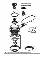
Page 13: ...r Assembly AP260 AP800002 AP800019 AP800006 AP800007 5 220 0 0 0 8 A M A 6 7 WH 220 7 1 0 0 0 8 P A 8 0 220 6 B 4 1 E P P 9 10 11 220 2 1 0 0 0 8 P A HDWFP8000 12 15 Ball Downrod Assembly 4 5 Canopy Motor Coupling Cover Assembly Fan Motor Assembly Hous Glass P800009OP ing Light Kit Assembly AP800008 Socket Assembly Light Bulb 60 Watt Blade Arm Set Blade Set Lower Steel Cap Assembly Bag Assembly Lo...

Page 14: ...14 1 2 3 4 7 6 8 9 13 5 15 10 11 NOTE The illustration shown is not to scale or its actual configurations may vary FP8000 220 Exploded View 14 13 ...

Page 15: ......

Page 16: ...Copyright 2010 2010 07 10983 Bennett Parkway Zionsville IN 46077 Toll Free 888 567 2055 FAX 866 482 5215 Outside U S call 317 733 4113 Visit Our Fanimation Website www fanimation com ...

Reviews: