background image

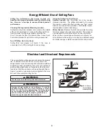
This  new ceiling fan will require a grounded electrical supply 
line  of  220-240  volts  AC, 50 Hz, 10 Amp circuit. The 


hanger bracket must be securely anchored and capable of 
supporting a load of least 60kg. If your fan is to replace an
existing ceiling light fixture, turn electricity off at the main
fuse box at this time and remove the existing light fixture.
Figure 1 depicts a typical structural configuration that may
be used for securely mounting the fan.

ʆ

WARNING

Turning off wall switch is not sufficient.  To avoid 
possible electrical shock, be sure electricity is turned 
off at the main fuse box before wiring.  All wiring must 
be in accordance with AS/NZS 3000 “The Wiring Rules” 
and the ceiling fan must be properly grounded as a  
precaution against possible electrical shock.

ʆ

WARNING

This fan must be installed by a licensed electrician. 

Electrical and Structural Requirements

s

n

a

F


g

n

il

i

e

C

 f

o


e

s

U

 t

n

e

i

c

 if

f

E


y

g

r

e

n

E

Ceiling fan performance and energy savings rely 
heavily on the proper installation and use of the ceiling 
fan.  Here are a few tips to ensure efficient product 
performance.

Choosing the Appropriate Mounting Location

Ceiling fans should be installed, or mounted, in the middle 
of the room and at least 2.1 m above the floor and 50 cm 


 from the walls. If ceiling height allows, install the fan 

2.4-2.7 m above the floor for optimal airflow. Consult your 


Fanimation Retailer for optional mounting accessories.

Turn Off When Not in the Room

Ceiling fans cool people, not rooms. If the room is 
unoccupied, turn off the ceiling fan to save energy.

Using the Ceiling Fan Year Round
Summer Season:

 Use the ceiling fan in the counter-

clockwise direction.  The airflow produced by the ceiling 
fan creates a wind-chill effect, making you “feel” cooler. 
Select a fan speed that provides a comfortable breeze, 
lower speeds consume less energy.

Winter Season:

 Reverse the motor and operate the ceiling 

fan at low speed in the clockwise direction. This produces 


a gentle updraft, which forces warm air near the ceiling 


down into the occupied space. Remember to adjust your  


air conditioner when using your ceiling fan-additional energy 
and dollar savings could be realized with this simple step!

Ceiling

Ceiling

Joists

Ceiling

Joists

Figure 1

50 X 100 mm
Timber Batten
Between Joists

4

Summary of Contents for FPD8148AU Series

Page 1: ...Model No FPD8148 AU OWNER S MANUAL READ AND SAVE THESE INSTRUCTIONS Ceiling Fan Net Weight 14 6 kg The Odyn ...

Page 2: ...oduct and or accessories designated specifically for use with this product Using parts and or accessories not designated for use with this product will void your warranty and could result in personal injury or property damage WARNING To reduce the risk of personal injury do not bend the blade bracket flange or blade holder when installing the brackets balancing the blades or cleaning the fan Do no...

Page 3: ...YHQLHQFH FKHFN RII HDFK VWHS V HDFK VWHS LV FRPSOHWHG SODFH D FKHFN PDUN 7KLV ZLOO HQVXUH WKDW DOO VWHSV KDYH EHHQ FRPSOHWHG DQG ZLOO EH KHOSIXO LQ QGLQJ RXU SODFH VKRXOG RX EH LQWHUUXSWHG LULQJ DQG FRQQHFWRUV PXVW EH RI W SH UHTXLUHG E ORFDO UHJXODWLRQV 7KH PLQLPXP ZLUH ZRXOG EH D FRQGXFWRU ZLUH ZLWK JURXQG Tools Needed for Assembly Materials NOTE If you are uncertain of part description refer to...

Page 4: ...ng fan Here are a few tips to ensure efficient product performance Choosing the Appropriate Mounting Location Ceiling fans should be installed or mounted in the middle of the room and at least 2 1 m above the floor and 50 cm from the walls If ceiling height allows install the fan 2 4 2 7 m above the floor for optimal airflow Consult your Fanimation Retailer for optional mounting accessories Turn O...

Page 5: ... aligning the holes in the downrod support with holes in the downrod Secure clevis pin with hairpin clip Tighten the two set screws with nuts in the downrod support Figure 4 WARNING It is critical that the clevis pin in the downrod support is properly installed and the set screws and nuts are securely tightened Failure to do so could result in the fan falling 2 Remove the hairpin clip and clevis p...

Page 6: ... ball on the downrod as follows Route the three 2m length wires and safety cable through the hanger ball Position the pin through the two holes in the downrod and align the hanger ball so the pin is captured in the groove in the top of the hanger ball Pull the hanger ball up tight against the pin Securely tighten the set screw in the hanger ball A loose set screw could create fan wobble Figure 6 A...

Page 7: ...r attach safety cable to ceiling joist or wood structural member The lag bolt will pass through the flat washer safety cable loop and into the building structure Figure 3 NOTE Ceiling support cable must be directly secured to ceiling joist or structural member using the x 2 lag bolt and flat washer Figure 3 3 Make sure the electrical supply wires including the hanger bracket earth wire and safety ...

Page 8: ...ow earth wire to the terminal block as shown in Figure 2 2 Securely connect the blue fan motor wire and the black supply neutral to the N terminal of the connec tor block as shown in Figure 2 3 Securely connect the brown fan motor wire and the red Active supply wire to the L terminal of the connector block as shown in Figure 2 After connections have been made carefully push leads into the recess m...

Page 9: ...when installing balancing the blades or cleaning the fan Do not insert foreign objects in between the rotating blades WARNING To reduce the risk of electric shock disconnect the electrical supply circult to the fan before installing light kit CAUTION Z 3 16Ŋ Pan Head Serrated Screw HARDWARE USED 1 Lay flat side of blade holder on a flat surface with the inside of the blade holder arm facing up Thi...

Page 10: ...ight kit Assemble the steel cap assembly to the adapter steel cap by twisting in a clockwise direction Figure 2B Light Plate Assembly Figure 4 To reduce the risk of electric shock disconnect the electrical supply circult to the fan before installing light kit CAUTION NOTE If you have installed your fan with the steel cap skip steps 3 and 4 LED Assembly Light Plate Assembly Figure 3 4 Secure the gl...

Page 11: ...is complete The fan is now ready for normal use 2 To make the fan operational install 23A 12V battery included into the hand held remote transmitter If not used for long periods of time remove the battery to prevent damage to the transmitter With fan power off Then follow the remote code setting process Store the remote away from excessive heat or humidity Figure 2 Figure 2 11 How to Operate Your ...

Page 12: ...ows I minimum speed II low speed III medium low speed IV medium speed V medium high speed VI high speed Figure 4 Fan speed Turns the fan off Controls fan direction forward and reverse Figure 4 Maintenance Periodic cleaning of your new ceiling fan is the only maintenance that is needed When cleaning use only a soft brush or lint free cloth to avoid scratching the finish Abrasive cleaning agents are...

Page 13: ...e 3 FAN WOBBLES EXCESSIVELY 1 Tighten both setscrews securely in downrod support 2 Tighten the setscrew in the downrod hanger ball assembly 3 Check to be sure screws which attach the fan blade holders to the blades are tight 5 Tighten the hanger bracket screws to the outlet box and secure outlet box 6 Balance blades using balance kit provided in hardware bag 1 Setscrew in downrod support is loose ...

Page 14: ...No FPD8148 AU Reference Description Part 1 A R1 1 2 3 1 3 4 33 1 0otor Coupling Cover 5 3 1 0 1 8 Blade Cover Set DQ 0RWRU VVHPEO 6 AP814809 Blade Set 7 3 1 3 1 AP814814 220 3 AP26 1 Blade Holder Set 8 LJKW 3ODWH VVHPEO 9 ODVV VVHPEO Steel Cap Assembly 10 3 1 Adapter Steel Cap 3 1 Hand Held Remote 75 1 Receiver 5 2 67 11 12 13 14 3 1 8 16 15 3KLOOLSV 6FUHZGULYHU Ý RRVH DUGZDUH DJ ODGH 0RXQWLQJ DUG...

Page 15: ...148 AU Exploded View NOTE The illustration shown is not to scale or its actual con guration may vary Product parts are subject to change without notice Figure 1 1 2 3 4 5 6 7 8 16 14 9 12 10 11 The Odyn 16 16 13 15 ...

Page 16: ...ectrician s details Do not uninstall or attempt to return the product to the supplier or MyFan unless advised to by MyFan You must be the original purchaser of the product and it must be installed in its original point of installation to be covered by this warranty Warranty periods begin from the date of purchase Because of varying climate conditions this warranty does not cover changes in finish ...

Page 17: ...Copyright 2015 Fanimation 2015 10 V 01 Distributed in Australia by MyFan Pty Ltd www myfan com au ...

Reviews: