


Summary of Contents for Involution FP4520 Series
Page 15: ......
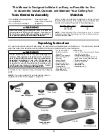
The Fanimation Involution FP4520 Series ceiling fan combines modern design with high-performance technology. Ensure you get the most out of your fan by downloading the free Owner's Manual from 88.208.23.73:8080. This comprehensive manual provides step-by-step instructions for installation, operation, and maintenance of your fan, making it a must-have resource.
Page 15: ......


