


6
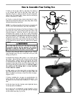
How to Hang Your Ceiling Fan
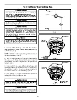
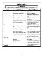
Figure 1
Floor
Ceiling
No
less than
7 ft
▲
WARNING
The fan must be hung with at least 7´ of clearance from
floor to blades (Figure 1)
▲
WARNING
The outlet box must be securely anchored and capable
of withstanding a load of at least 50 lbs. Hanger bracket
must seat
fi
rmly against outlet box. If the outlet box is
recessed, remove wallboard until bracket contacts box.
If bracket and/or outlet box are not securely attached,
the fan could wobble or fall.
CAUTION
Do not connect fan blades until the fan is completely
installed. Hanging fan with blades connected may result
in damage to the fan blades.
▲
WARNING
To avoid possible electrical shock, be sure electricity is
turned off at the main fuse box before hanging.
NOTE: If you are not sure if the outlet box is grounded,
contact a licensed electrician for advice, as it must be
grounded for safe operation.
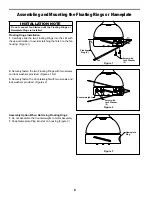
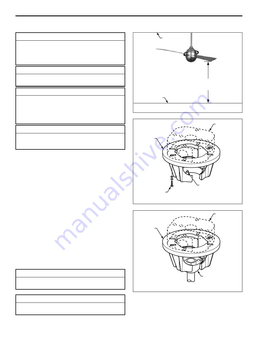
Figure 3
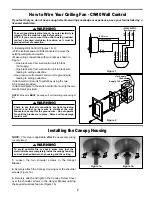
Figure 2
Outlet Box
Hanger
Bracket
Outlet Box
Hanger
Bracket
Screw (2)
Supplied with
Outlet Box
Tab
Downrod/Hanger
Ball Assembly
▲
WARNING
Failure to seat tab in groove could cause damage to
electrical wires and possible shock or fire hazard.
▲
WARNING
To avoid possible shock, do not pinch wires between the
downrod/hanger ball assembly and the hanger bracket.
1.
Securely attach the hanger bracket to the outlet box
using the outlet box screws and washers supplied with the
outlet box (Figure 2).
NOTE:
Outlet box screws pass through slotted holes of
the hanger bracket (Figure 2).
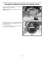
2.
Pull the electric wires in the outlet box down through
the opening in the hanger bracket and bend wires up and
out of the way so that the hanger ball will easily fit into the
hanger bracket.
3.
Carefully lift the fan and seat the downrod/hanger ball
assembly on the hanger bracket that was just attached to
the outlet box (Figure 3). Be sure the groove in the ball is
lined up with tab on the hanger bracket (Figure 2).
4.
After splicing, the wiring should be turned upward and
pushed carefully up into the outlet box.
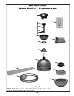
Summary of Contents for Involution FP4520 Series
Page 15: ......


