
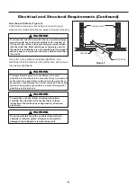


How to Hang and Wire Your Ceiling Fan (Continued)
8
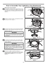
NOTE:
The remote unit has 32 different code
combinations. To prevent possible interference
from or to other remote units, simply change the
combination code in the remote and receiver.
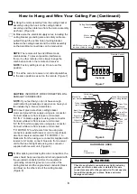
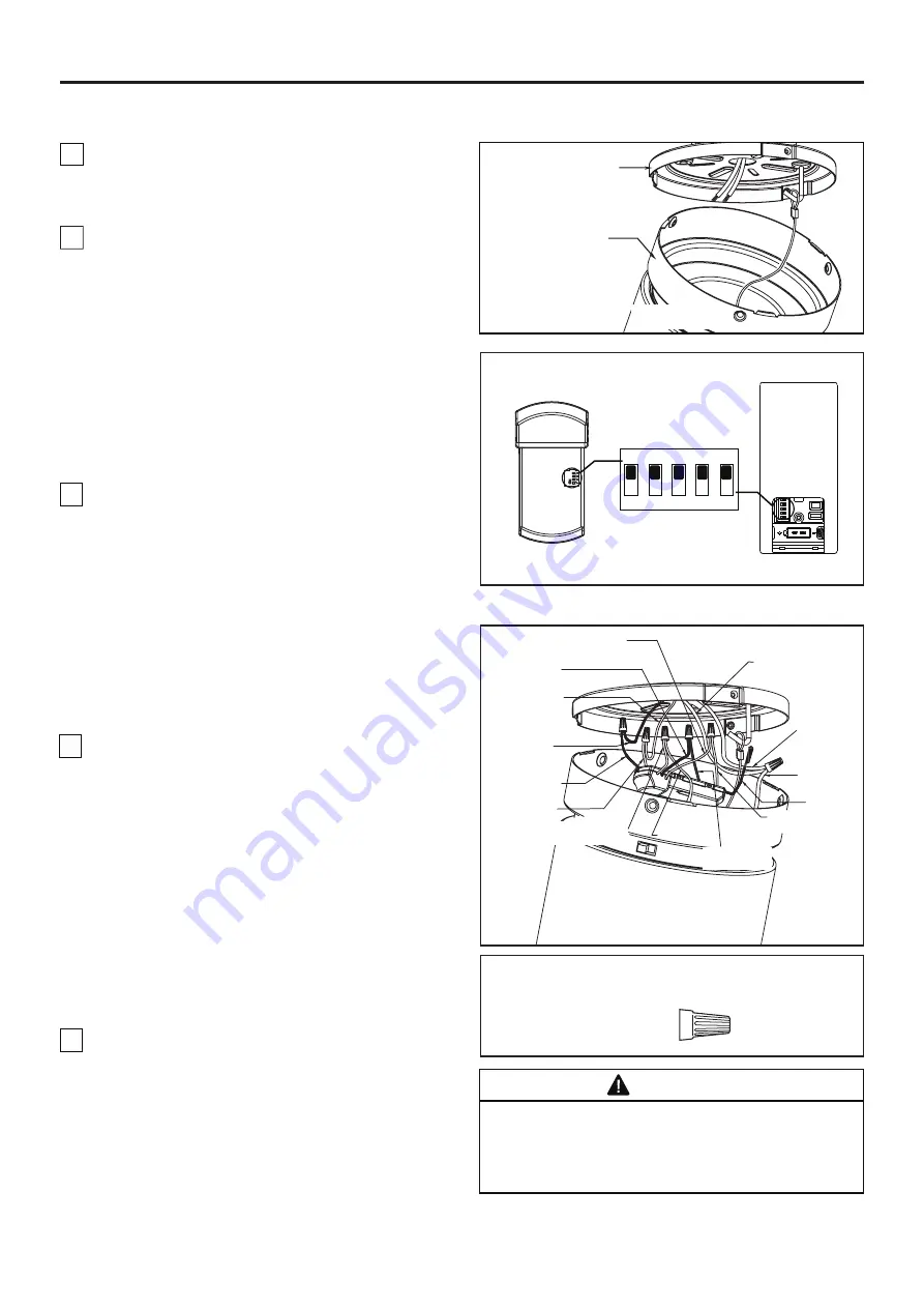
7.
To set the code on receiver unit, slide dip switches
to the same positions as set on the remote. (Figure 7)
NOTE:
Factory setting is all up. Do not use this
position.
x 6
Wire
Connectors
HARDWARE USED:
CAUTION:
INCORRECT WIRE CONNECTION WILL
DAMAGE THIS RECEIVER.
NOTE:
If you feel that you do not have enough
electrical wiring knowledge or experience, have your
fan installed by a licensed electrician.
WARNING
Check to see that all connections are tight, including
ground, and that no bare wire is visible at the wire
connectors except for the ground wire. Do not operate
fan until the blades are in place. Noise and motor
damage could result.
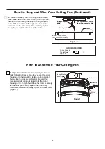
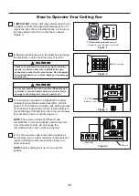
9.
After splicing and making the wire connections, the
wires should be spread apart and turned upward with
the grounded conductor (white), the equipment
-grounding conductor (green) on one side of the
ceiling bracket and the ungrounded conductor (black
and blue) on the other side of the ceiling bracket.
(Figure 8)
White Wire
from Supply
Black Wire
from Receiver
White Wire
from Receiver
BLK_ANT
Green Wire (Ground)
from Ceiling Bracket
Green Wire
(Ground)
from Supply
Black Wire
from Receiver
Black Wire
from Supply
White Wire
from Motor
Green Wire
(Ground)
from Motor
Blue Wire
from Motor
NOTE:
Supply wires and
fan wires omitted for clarity
Ceiling Bracket
Assembly
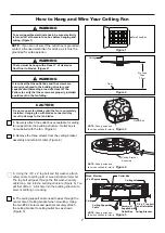
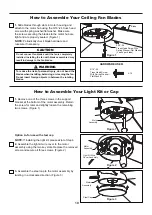
5.
Hang the motor assembly from the ceiling bracket
assembly using the hook on the ceiling bracket
assembly and the cable loop from the motor assembly
as shown. (Figure 6)
Figure 6
Motor
Assembly
Figure 7
Figure 8
White Wire
Blue Wire
from Receiver
from Receiver
Black Wire
from Motor
6.
Make sure the electrical supply wires, including the
ceiling bracket grounding wire and safety cable are
pulled through the center hole of ceiling bracket,
between the ceiling bracket and the motor assembly
so that electrical connections can be made later.
8.
Connect green wires from ceiling bracket,
motor and ground from supply using wire connector.
Connect black wire from receiver unit marked
“AC IN L” to black supply wire using wire connector.
Connect white wire from receiver unit marked
“AC IN N” to white supply wire using wire connector.
Connect white wire from receiver unit marked
“TO MOTOR N” to white wire from fan using wire
connector supplied with receiver unit. Connect black
wire from receiver unit marked “TO MOTOR L” to
black wire from fan using wire connector supplied with
receiver unit. Lastly, connect blue wire from receiver
unit to the blue fan light wire using wire connector
supplied with receiver unit. (Figure 8)
Dip Switch
Receiver
Remote Control
ON DIP
1
2
3
4
5
Summary of Contents for KWARTET FPS8553 Series
Page 17: ......


