background image

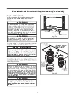
8. CAUTION:  To reduce the risk of personal injury, mount the fan head assembly to a ceiling joist or structural member using 

9. This fan is to be used in dry location only.

    the hardware provided with your fan. 

Important Safety Instructions

WARNING:

To avoid fire, shock and serious personal injury, follow these instructions.

1. Read your owner’s manual and safety information before installing your new fan. Review the accompanying assembly

diagrams.

2. Before servicing or cleaning unit, switch power off at service panel and lock service panel disconnecting means to prevent

power from being switched on accidentally. When the service disconnecting means cannot be locked, securely fasten a
warning device, such as a tag, to the service panel.

3. Be careful of the fan and blades when cleaning, painting, or working near the fan. Always turn off the power to the ceiling

fan before servicing.

4. Do not insert anything into the fan blades while the fan is operating.

Additional Safety Instructions

1. To avoid possible shock, be sure electricity is turned off at the fuse box before wiring, and do not operate fan without

blades.

2. All wiring and installation procedures must satisfy National Electrical Codes (ANSI/ NFPA 70-1999) and Local Codes. The

ceiling fan must be grounded as a precaution against possible electrical shock. Electrical installation should be made or
approved by a licensed electrician.

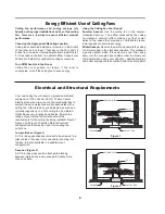
3. The complete fan must be securely mounted and capable of reliably supporting at least 50 lbs. (fan and accessories not to

exceed 50 lbs. or 22.70 kgs.). See page 6 of owner’s manual for support requirements. Consult a qualified electrician if in
doubt.

4. The fan must be mounted with the fan blades at least 7 feet from the floor to prevent accidental contact with the fan blades.
5. Follow the recommended instructions for the proper method of wiring your ceiling fan. If you do not have adequate

electrical knowledge or experience, have your fan installed by licensed electrician.

6. Suitable for use with solid-state speed controls.

TO REDUCE THE RISK OF ELECTRIC SHOCK, THIS FAN MUST BE INSTALLED WITH A GENERAL USE, 

ISOLATING WALL CONTROL/SWITCH.

WARNING:

WARNING:

This product is designed to use only those parts supplied with this product and/or accessories designated

specifically for use with this product. Using parts and/or accessories not designated for use with this product could result in
personal injury or property damage.

WARNING:

To reduce the risk of personal injury, do not bend the blade bracket (flange or blade holder) when installing the

WARNING:

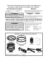
Motor assembly mount to an outlet box marked acceptable for fan support.

WARNING:  

Do not operate this fan with a variable (Rheostat) wall controller or dimmer switch. Doing so could result in 

damage to the ceiling fan's remote control unit.

WARNING:  

To reduce the risk of fire, electric shock, and injury to persons, ceiling-suspended fan, model FP7966 series must 

be installed with fan head assembly that are marked on their cartons to indicate the suitability with this model. Other fan head 
assembly cannot be substituted. 


brackets, balancing the blades, or cleaning the fan. Do not insert foreign objects in between rotating fan blades.

LIMITED LIFETIME WARRANTY

Extends to the original purchaser of a Fanimation Fan

1. LIMITED LIFETIME MOTOR WARRANTY - If any part of your fan motor fails, due to a defect in materials or workmanship

during the lifetime of the original purchaser, Fanimation will provide the replacement part free of charge, when the defective
fan is returned to our national service center. Proof of purchase is required. Customer shall be responsible for all costs
incurred in the removal or reinstallation and shipping of the product for repairs or replacement.

2. ONE YEAR MOTOR LABOR WARRANTY - If your fan motor fails at any time within one year from the original purchase, due

to defects in materials or workmanship, labor to repair the motor will be provided free of charge at our national service
center. Purchaser will be responsible for labor charges after this one-year period. Customer shall be responsible for all
costs incurred in the removal or reinstallation and shipping of the product for repairs or replacement.

3. If any other part of your fan fails at any time within one year after original purchase, due to a defect in materials or

workmanship, we will repair, or replace, at our option, the defective part free of charge for parts and labor performed at our
national service center.

This device complies with Part 15 of the FCC Rules. Operation is subject to the following two conditions: 
(1) This device may not cause harmful interference, and (2) this device must accept any interference received, including 
interference that may cause undesired operation. If the intentional radiator can be classified as a Class B digital device or a PC 
peripheral, then shall include the following or equivalent:

Note:

 This equipment has been tested and found to comply with the limits for Class B digital device, pursuant to part 15 of the 

FCC Rules. These limits are designed to provide reasonable protection against harmful interference in a residential installation.
This equipment generates, uses and can radiate radio frequency energy and, if not installed and used in accordance with the
instructions, may cause harmful interference to radio or television reception, which can be determined by turning the 
equipment off and on, the user is encouraged to try to correct the interference by one or more of the following measures:
- Reorient or relocate the receiving antenna. 
- Increase the separation between the equipment and the receiver.
- Connect the equipment into an outlet on a circuit different from that to which the receiver is connected.
Consult the dealer or an experienced radio/TV technician for help. 

Note:

 For a Class A digital device, statements of 15. 105(a) must be included when appropriate for the device in question.    

6. The appliance is not intended for use by young children or infirm persons without supervision. Young children should be 

supervised to ensure that they do not play with the appliance.

7.   For supply connections, if the conductor of a fan is identified as a grounded conductor, then it should be connected to a 
grounded conductor power supply. If the conductor of a fan is identified as an ungrounded conductor, then it should be 
connected to an ungrounded conductor power supply. If the conductor of a fan is identified for equipment grounding, then it 
should be connected to an equipment-grounding conductor.          

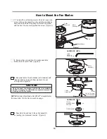
5. Do not operate reversing switch until fan blades have come to a complete stop.

Summary of Contents for MA7966

Page 1: ...e For Fan Head Assembly HA7966 Net Weight 2 4 kg 5 29 lbs B7966 Net Weight 0 60 kg 1 32 lbs MA7966 Net Weight 9 3 kg 20 48 lbs OWNER S MANUAL READ AND SAVE THESE INSTRUCTIONS The Kellan Belt Driven Ceiling Fans Model No MA7966 Motor Series Model No HA7966 Fan Series Model No B7966 Fan Blade FP7966 ...

Page 2: ...ED LIFETIME WARRANTY Extends to the original purchaser of a Fanimation Fan 1 LIMITED LIFETIME MOTOR WARRANTY If any part of your fan motor fails due to a defect in materials or workmanship during the lifetime of the original purchaser Fanimation will provide the replacement part free of charge when the defective fan is returned to our national service center Proof of purchase is required Customer ...

Page 3: ...by law This warranty gives you special legal rights and you may also have other rights that vary from state to state 10 A certain amount of wobble is normal and should not be considered a problem or a defect 8 Under no circumstances may a fan be returned without prior authorization from Fanimation The receipt of purchase must accompany authorized returns and must be sent freight prepaid to Fanimat...

Page 4: ...ration Figure 1 page 17 Check to see that you have received the following parts Hand held Remote Motor Assembly Ceiling Plate Assembly Housing Assembly MA7966 Motor Assembly and Hardware Parts Identification NOTE The illustration shown is not to scale or its actual configuration may vary Parts and packings subject to change without notice Figure 1 ʆWARNING Before assembling your ceiling fan refer ...

Page 5: ...cription refer to exploded view illustration Figure 2 page 19 NOTE Optional Wood Blade Set B7966 is available for this assembly Not for Damp Location usage Head Assembly Unpacking Instructions and Parts Identification Hardware bag 1 Check to see that you have received the following parts DUGZDUH EDJ 3XOOH VVHPEO Belt 3LORW ROH 3DSHU LYH DJ EROW Ý Ý LYH ODW ZDVKHU PP OOHQ UHQFK Ý PP OOHQ UHQFK PP 6...

Page 6: ...a gentle updraft which forces warm air near the ceiling down into the occupied space Remember to adjust your thermostat when using your ceiling fan additional energy and dollar savings could be realized with this simple step Electrical and Structural Requirements Your new ceiling fan will require a grounded electrical supply line of 120 volts AC 60 HZ 15 Amp Circuit Electrical code requires use of...

Page 7: ... fuse box at this time and remove the existing light xture Turning off wall switch is not sufficent To avoid possible electrical shock be sure electricity is turned off at the main fuse box before wiring All wiring must be in accordance with National and Local codes and the ceiling fan must be properly grounded as a precaution against possible electrical shock Follow all wiring instructions carefu...

Page 8: ...gure 4 Figure 4 ʆWARNING The outlet box must be securely anchored and capable of withstanding a load of at least 35 lbs Hanger bracket must seat rmly against outlet box If the outlet box is recessed remove wallboard until bracket contacts box If bracket and or outlet box are not securely attached the fan could wobble or fall ʆ 8 How to Hang and Wire Your Motor Assembly x 4 x 4 FLAT WASHER PAN HEAD...

Page 9: ...r Figure 7 After splicing and making the wire connections the wires should be spread apart and turned upward with the grounded conductor and the equipment grounding conductor on one side of the outlet box and the ungrounded conductor on the other side of the outlet box 9 How to Hang and Wire Your Motor Assembly continued If you feel that you do not have enough electrical wiring knowledge or experi...

Page 10: ...flat washers and securely tighten all hex nuts Figure 8 8 Assemble the housing to ceiling plate assembly using the previously removed screws and securely tighten all screws Figure 9 Housing Figure 9 How to Hang and Wire Your Motor Assembly continued 10 Figure 8 Motor Assembly Ceiling Plate Assembly ...

Page 11: ...W WKH SXOOH DVVHPEO RQ WKH FHLOLQJ ZLWK Ý Ý lag bolts and flat washers The lag bolt will pass through the flat washer and into the building structure Figure 3 Pulley Assembly Mounting Cover Allen Wrench Plywood Pilot Hole Paper ALLEN WRENCH 1 8Ŋ x 60 x 20 mm HARDWARE USED x 4 x 4 FLAT WASHER LAG BOLT HARDWARE USED Ŋ Z Ŋ 4 Assemble the pulley assembly mounting cover using the previously removed scr...

Page 12: ...ould hold the belting together after releasing the belt Figure 1 2 Punch two holes approximately 1 8 inch in diameter through the overlapping belts spacing them one inch apart with the punch tool supplied Figure 2 3 Using the rivets rivet washers and the rivet tool SURYLGHG LQVWDOO WZR ULYHWV 7KH ÀDW KHDG RI WKH ULYHW must be on the inside of the belt the side touching the pulley while the rivet w...

Page 13: ...n Blades Pulley Motor Assembly Assembly Allen Wrench Belt Figure 2 Figure 4 Figure 3 HARDWARE USED 3 16Ý 24 Screws 3 per assembly x 6 x 6 FIBER WASHER 3 16Ŋ 24 WASHER HEAD SCREWS 3 Securely fasten the two blades not included with washer head screws with fiber washers Do not over tighten Figure 3 4 Assemble the end cap to the pulley assembly by twisting in a clockwise direction Figure 4 CAUTION Do ...

Page 14: ...ecurity systems simply change the combination code in your transmitter and receiver To set the code perform these steps 7UDQVPLWWHU remove battery cover by pressing firmly below arrow and sliding battery cover off Slide code switches to your choice of up or down position Factory setting is all up Do not use this position With a small screwdriver or ball point pen slide switches up or down Figure 2...

Page 15: ...r the screw holes Including in the control Figure 1 1 Unthread two screws from the wall switch plate Figure 1 2 Install the control bracket with two 6 32x 1 screws And push the four plastic plug to cover the screw holes Including in the control Figure 2 1 Unthread two screws from the wall switch plate Figure 1 2 Install the control bracket with two 6 32x 3 4 screws And push the four plastic plug t...

Page 16: ...d state controls are not recommended choose an alternative control method CAUTION Make sure main power is turned off 4 Tighten set screw securely 5 Not considered a defect 3 FAN WOBBLES EXCESSIVELY 1 Fan Motor base lag bolts on the ceiling is loose 2 Blade holders not seated properly 1 Tighten lag bolts securely 2 Check to be sure the fan blade holders seat firmly and uniformly to the surface of t...

Page 17: ...e illustration shown is not to scale or its actual configuration may vary Wires partially removed for clarity Insert FINISH CODES Refer to fan model number located on fan assembly Exploded View Motor Assembly MA7966 5 4 6 7 10 9 ...

Page 18: ...ail store for repair parts When ordering repair parts always give the following information 3DUW 1XPEHU 3DUW HVFULSWLRQ DQ 0RGHO 1XPEHU 2 0RWRU VVHPEO 0 1 HLOLQJ 3ODWH VVHPEO 3 RXVLQJ VVHPEO 3 Rivet Tool 4 3 3 3XQFK 7RRO 3 HOW ODPS 3 Hand Held Remote Harness Wiring Capacitor TR33WH 3 Receiver 5 1 Hardware Bags Containing LUH RQQHFWRUV Ý 3DQ HDG RRG 6FUHZ 7 SH ODW DVKHU 0 Motor Assembly MA7966 3KLO...

Page 19: ...Description Part How To Order Parts Contact your retail store for repair parts When ordering repair parts always give the following information 3DUW 1XPEHU 3DUW HVFULSWLRQ DQ 0RGHO 1XPEHU 2 Belt 0 3LORW ROH 3DSHU 3 1 3XOOH VVHPEO 3 4 Hardware Bags Containing Blade Mount Hardware Bag Containing Lag Bolt 1 4Ý x 2Ý 5 ODW DVKHU Ø Ø PP OOHQ UHQFK Ý PP OOHQ UHQFK PP Washer HDG 6FUHZ Ý LEHU DVKHU Ý Ref D...

Page 20: ...10983 Bennett Parkway Zionsville IN 46077 Toll Free 888 567 2055 FAX 866 482 5215 Outside U S call 317 733 4113 Visit Our Website www fanimation com Copyright 2014 Fanimation 2014 09 V 01 ...

Page 21: ...7966 0 60 kg 1 32 lbs Apropiado para su uso con controles de velocidad de estado sólido ADVERTENCIA Soporte directamente desde la estructura del edificio para el unidad del cabezal Modelo N º MA7966 Unidad del motor Modelo N º HA7966 Unidad del cabezal Modelo N º B7966 Juego de aspas MANUAL DEL PROPIETARIO LEA Y GUARDE ESTAS INSTRUCCIONES FP7966 ...

Page 22: ...ndio descarga eléctrica y lesiones a personas Ventilador serie MA7966 Modelo Colgado del techo debe ser instalado con unidad del cabezal que se marcan en sus cartones señalar la adecuación a este modelo Otras unidad del cabezal no puede ser sustituido PARA REDUCIR EL RIESGO DE DESCARGAS ELÉCTRICAS ESTE VENTILADOR SE DEBE INSTALAR CON UN CONTROL INTERRUPTOR DE PARED AISLADO ADVERTENCIA Este product...

Page 23: ...es posible que también goce de otros derechos que pueden variar según el estado 10 Es normal que se produzca un cierto movimiento oscilante y esto no debe considerarse un problema o defecto GARANTÍA LIMITADA DE POR VIDA Se extiende al comprador original de un ventilador Fanimation 7 Fanimation se reserva el derecho de modificar o discontinuar un producto en cualquier momento o sustituir cualquier ...

Page 24: ...sta autorizado para instalar el ventilador L ó é y q ó g má q ñ xó g m ñ NOTA coloque las piezas de las bolsas de piezas individuales en un contenedor pequeño para evitar que se extravíen Si faltan piezas pón gase en contacto con su proveedor local Materiales A W 12 A 24 Mano a distancia Unidad del motor Unidad de placa para el techo Unidad del Carcasa Figure 1 Pinzas de la correa Remachadora Perf...

Page 25: ...VLQ SUHYLR DYLVR 25 Figura 2 Unidad del cabezal Instrucciones de desembalaje e identificación de las piezas Bolsas de accesorios 1 Verifique que haya recibido las siguientes piezas Bolsas de accesorios Unidad del polea Correa Papel piloto para orificio Unidad del polea Correa Papel piloto para orificio LQFR WLUDIRQGRV GH Ý Cinco arandela plana de Ø6 5 x Ø16 x 1 mm Llave Allen GH Ý PP Llave Allen G...

Page 26: ...amosalgunassugerencias para asegurar un rendimiento eficiente del producto Selección del lugar de montaje adecuado Los ventiladores de techo se deben instalar en el centro de la habitación a 2 13 m 7 pies de altura del piso como mínimo y 0 5 m 18 pulgadas de las paredes Si la altura del techo lo permite instale el ventilador a 2 5 m 8 9 pies por encima del suelo para un flujo de aire óptimo Consul...

Page 27: ...LGDG GH PRWRU QR IXQFLRQDUi PiV GH FXDWUR FDEH DO PRQWDMHV GH OiPLQD NOTA LA INSTALACIÓN 27 Requisitos eléctricos y estructurales cont Figura 3 Techo Vigas del techo Caja de distribución eléctrica Profunda caja con aparato ortopédico Figura 3 Conectado a una caja de distribución eléctrica este colgador sirve para abarcar el espacio entre dos vigas y ocupar el lugar de bloqueo de la madera ADVERTEN...

Page 28: ...madera de cabeza plana de Z Ŋ Aditamentos utilizados 2 Extraiga los cuatro tornillos y las tuercas hexagonales con arandela plana Guárdelos para la reinstalación en los pasos 7 y 8 de la página 30 Figura 3 NOTA Se omiten los cables de suministro para mayor claridad Caja de distribución eléctrica Se recomienda que cada ventilador y el motor tiene el UHVSDOGR GH PDGHUD FRQWUDFKDSDGD GH ô Ý DVHJXUDGR...

Page 29: ...e pelado o un cable verde con aislamiento Conecte los cables con cuidado usando un conector de cables Conecte con cuidado el cable del receptor blanco que viene del ventilador con el cable blanco neutro de la fuente de alimentación utilizando un conector de cables Por último conecte el cable negro del receptor que viene del ventilador al cable negro de la fuente de alimentación utilizando un conec...

Page 30: ... de techo utilizando las tuercas hexagonales y arandelas planas anteriormente extraídas y fíjelas adecuadamente Figura 8 8 Instale la carcasa a la Unidad de placa para el techo de techo utilizando los tornillos anteriormente extraídos y fíjelos adecuadamente Figura 9 Carcasa Cómo instalación y cableado del ventilador de techo cont ...

Page 31: ... HARDWARE USED x 4 x 4 Arandelas planas Tirafondos Aditamentos utilizados Ŋ Z Ŋ 4 Instale la carcasa de montaje de la unidad del polea utilizando los tornillos anteriormente extraídos y fíjelos todos de nuevo adecuadamente Figura 4 Figura 4 Figura 1 Figura 2 Unidad del polea Figura 3 3 Q SULPHU OXJDU WDODGUH ORV RULILFLRV JXtDV GH Ý HQ la base de contrachapado o viga de sujeción para evitar que se...

Page 32: ...tremos de la correa y tire con fuerza Las pinzas deberían seguir sujetando la correa después de soltarla Figura 1 2 Perfore dos orificios de aprox 1 8 pulgadas de diámetro a través de las correas montadas dejando un espacio entre ambos orificios de una pulgada utilizando la perforadora suministrada Figura 2 3 Instale dos remaches utilizando la remachadora los remaches y las arandelas de remaches E...

Page 33: ... Figura 4 Figura 3 Aditamentos utilizados Aditamentos utilizados 2 por conjunto x 6 x 6 Arandela de fibra Tornillos de cabeza FG Ŋ 3 Asegure bien las aspas con tornillos de cabeza no incluido con tornillos de cabeza con arandela de fibra No ajuste demasiado Figura 3 4 Asegure el capuchón final de la unidad del polea girando en el de las agujas del reloj Figura 4 CAUTION Do not connect fan blades u...

Page 34: ...opción deslizando los interruptores de código hacia arriba o hacia abajo La configuración de fábrica es en la posición superior No utilice esta posición Con un destornillador pequeño o con una lapicera deslice firmemente hacia arriba o hacia abajo Figura 2 Vuelva a colocar la cubierta de la batería en el transmisor 1 Funcionamiento y uso del transmisor remoto Figura 1 Instale la batería de 3 volti...

Page 35: ...os tornillos Incluidos con el mando Figura 2 1 Retire los dos tornillos colocados en la plaza del interruptor de la pared Figura 1 2 Instale el soporte de control con los dos tornillos 6 32x 1 Empuje los cuatro tapones de plástico para cubrir los orificios de los tornillos Incluidos con el mando Figura 2 1 Taladre dos orificios de 1 4 en la pared y utilice los tacos de plástico M6 para colocarlos ...

Page 36: ...del ventilador estén bien ajustados PRECAUCIÓN Asegúrese de que el suministro principal de electricidad esté desconectado 3 Algunos motores de ventilador son sensibles a las señales de los controles de velocidad de estado sólido variables Los controles de estado sólido no son recomendables Escoja un método de control alternativo 4 Ajuste bien los tornillos 2 Asegúrese de que los soportes de las as...

Page 37: ...37 1 2 3 8 Figura 1 Unidad del motor de MA7966 5 4 6 7 10 9 Ilustración del despiece Introduzcas los CÓDIGOS de acabo Consulte el número de modelo del ventilador ubicado en la unidad del ventilador NOTA ...

Page 38: ...cabeza plana Ý 10 Tipo B Arandela plana 5 HDWMA7966 Unidad del motor de MA7966 HVWRUQLOODGRU 3KLOOLSV GH Ý Lista de piezas Antes de desechar los materiales de embalaje asegúrese de haber extraído todas las piezas Inserte los CÓDIGOS DE ACABADO consulte el número de modelo del ventilador que se encuentra en el soporte de barral Cómo hacer un pedido de piezas Al hacer un pedido de piezas de repuesto...

Page 39: ... Ý Arandela de 2 54 x 5 92 x 0 89 mm 8 Cómo hacer un pedido de piezas Al hacer un pedido de piezas de repuesto proporcione siempr e la siguiente información 1 PHUR GH SLH D HVFULSFLyQ GH OD pieza 1 PHUR GH PRGHlo del ventilador Póngase en contacto con su tienda para obtener las piezas de repuesto Aspa opcional NOTA la ilustración que se muestra no está hecha a escala y su con JXUDFLyQ UHDO SXHGH Y...

Page 40: ...014 Fanimation 2014 09 V 01 10983 Bennett Parkway Zionsville IN 46077 Llame sin cargo al 888 567 2055 FAX 866 482 5215 Desde fuera de los EE UU llame al 317 733 4113 Visite nuestro sitio Web en www fanimation com ...

Reviews: