

Si otra pieza del ventilador fallara dentro del período de un año a partir de la fecha de compra original debido a un defecto en los
3.
materiales o en la fabricación, repararemos o sustituiremos, según creamos conveniente, la pieza defectuosa sin cargo alguno en
nuestro centro de servicios nacional.
Debido a las diversas condiciones climáticas, esta garantía no cubre cambios en la terminación, incluidos oxidación, corrosión,
4.
falta de brillo o peladuras.
Esta garantía es nula y no se aplica a daños por instalación incorrecta, negligencia, accidentes, uso indebido, exposición al calor o
5.
a la humedad en exceso, o como resultado de cualquier modificación realizada al producto original.
Todos los gastos de remoción y reinstalación del ventilador son responsabilidad exclusiva del propietario, y no de la tienda que
6.
vendió el ventilador ni de Fanimation.
9. Se entiende que las reparaciones y las sustituciones son el único recurso disponible de Fanimation. No existe ninguna otra
garantía expresa o implícita. Por la presente, Fanimation niega todas las garantías implícitas, que incluyen, entre otras, la
comerciabilidad y la aptitud para determinado fin hasta donde la ley lo permita. Algunos estados no permiten limitaciones sobre las
garantías implícitas. Fanimation no se hará responsable por daños accidentales, resultantes o especiales derivados del uso o el
rendimiento del producto o en conjunción con éste, excepto en los casos en los que la ley así lo disponga. Esta garantía le otorga
derechos legales especiales y es posible que también goce de otros derechos que pueden variar según el estado.
10. Es normal que se produzca un cierto movimiento oscilante y esto no debe considerarse un problema o defecto.
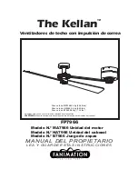
GARANTÍA LIMITADA DE POR VIDA
Se extiende al comprador original de un ventilador Fanimation
7. Fanimation se reserva el derecho de modificar o discontinuar un producto en cualquier momento, o sustituir cualquier pieza según
lo establecido por esta garantía.
8. En ningún caso se podrá devolver un ventilador sin previa autorización por parte de Fanimation. Las devoluciones autorizadas
deberán ir acompañadas del recibo de venta y deberán enviarse a Fanimation, previo pago del flete. El ventilador que se devuelva
deberá estar embalado en forma adecuada a fin de evitar daños durante el transporte. Fanimation no se hará responsable de los
daños que resulten del embalaje incorrecto del producto.
Tabla de contenidos
24
25
26
26
28
34
31
32
33
34
36
36
35
36
37
38
39
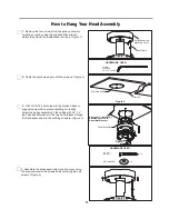
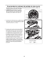
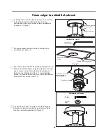
Cómo colgar la unidad del cabezal . . . . . . . . . . . . . . . . . . . . . . . . . . . . . . . . . . . . . . . . . . . . . .
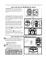
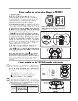
Cómo configurar su mando a distancia TR33WH . . . . . . . . . . . . . . . . . . . . . . . . . . . . . . . . . . .
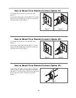
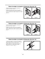
Cómo instalar su mando a distancia . . . . . . . . . . . . . . . . . . . . . . . . . . . . . . . . . . . . . . . . . . . . .
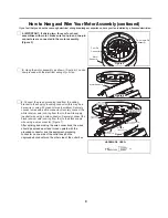
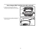
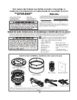
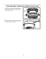
Unidad del motor-Instrucciones de desembalaje e identificación de las piezas . . . . . . . . . .
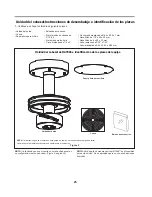
unidad del cabezal-Instrucciones de desembalaje e identificación de las piezas . . . . . . . . .
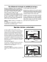
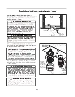
Requisitos eléctricos y estructurales . . . . . . . . . . . . . . . . . . . . . . . . . . . . . . . . . . . . . . . . . . . . .
8VRH¿FLHQWHGHODHQHUJtDHQYHQWLODGRUHVGHWHFKR
. . . . . . . . . . . . . . . . . . . . . . . . . . . . . . . .
Cómo
LQVWDODFLyQ\FDEOHDGRGHOYHQWLODGRUG
e
WHFKR
. . . . . . . . . . . . . . . . . . . . . . . . . .
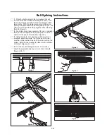
Instrucciones del ensamblaje de la correa. . . . . . . . . . . . . . . . . . . . . . . . . . . . . . . . . . . . . . . . .
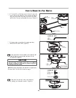
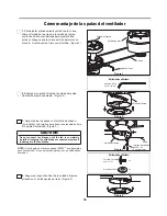
Cómo
PRQWDMHGHODVSDODVGHOYHQWLODGRU
. . . . . . . . . . . . . . . . . . . . . . . . . . . . . . . . . . . . .
Cómo instalar su de TR33WH mando a distancia
. . . . . . . . . . . . . . . . . . . . . . . . . . . . . . . . . . .
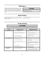
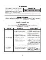
Mantenimiento . . . . . . . . . . . . . . . . . . . . . . . . . . . . . . . . . . . . . . . . . . . . . . . . . . . . . . . . . . . . . . .
Limpieza de las aspas . . . . . . . . . . . . . . . . . . . . . . . . . . . . . . . . . . . . . . . . . . . . . . . . . . . . . . . .
Solución de problemas . . . . . . . . . . . . . . . . . . . . . . . . . . . . . . . . . . . . . . . . . . . . . . . . . . . . . . . .
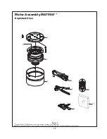
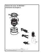
Ilustración del despiece
,
unidad del motor de MA7966
. . . . . . . . . . . . . . . . . . . . . . . . . . . . . . . .
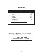
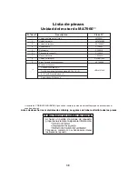
Lista de piezas, unidad del motor de MA7966
. . . . . . . . . . . . . . . . . . . . . . . . . . . . . . . . . . . . . . . . .
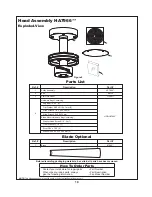
lustración del despiece y Lista de piezas, unidad del cabezal de HA7966 . . . . . . . . . . . . . . .


