11
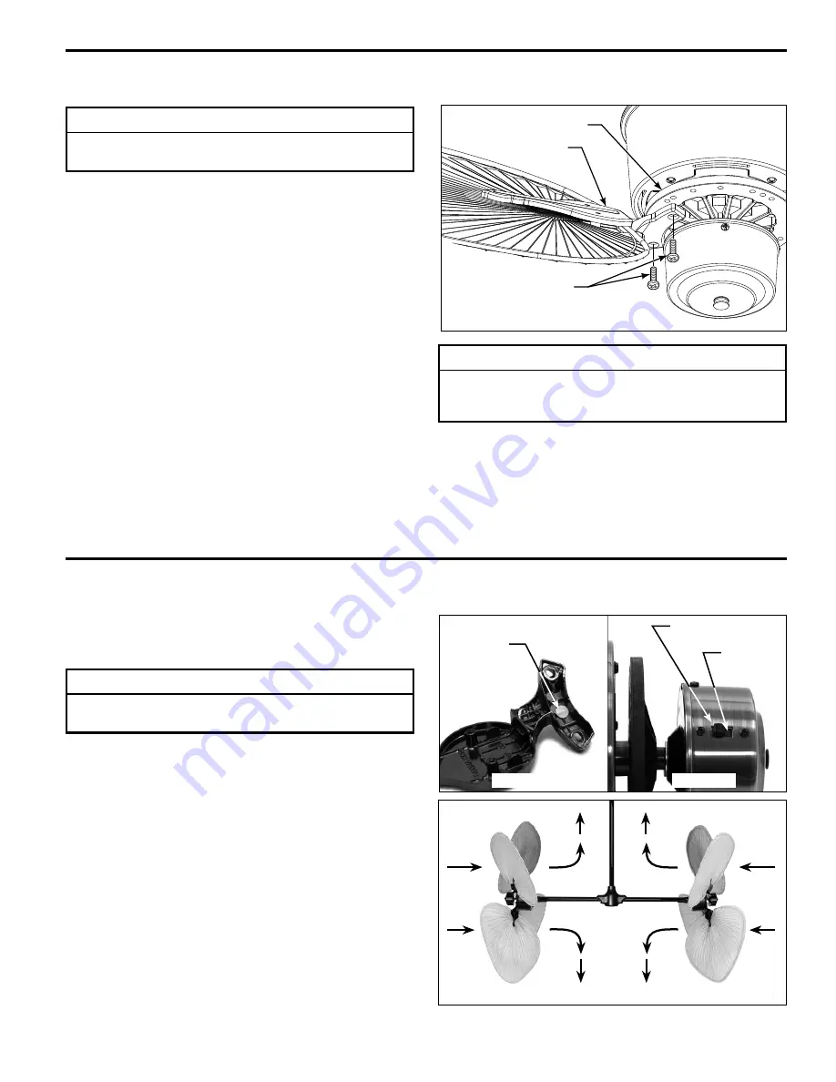
Controlling Airfl ow Patterns
Reversing Switch
Location
Figure 1a
Figure 2
Side A
Side B
Figure 1b
Color Code
Location
Color Code
Location
Figure 2:
Side A
Reversing Switch Setting - with Red Dot
Blade Arm Set - with Red Dot
Side B
Reversing Switch Setting - with White Dot
Blade Arm Set - with White Dot
NOTE: Choose one of the following color code blade &
switch set-up combinations for the desired airflow direction
as shown.
INSTALLATION NOTE
This section is applicable after the fan and the blades are
completely installed.
1.
Note the locations of the color code on the blade arm
and the reversing switch. (Figures 1a & 1b)
1.
Blade holders come packed in two different bundles, one
blade holder set is marked with a red dot (4 pcs) and one
blade holder set is marked with white dot (4 pcs). These
colored dots indicate which motor switch set-up (red or
white dot) to attach these blade holders to.
2.
Using the HDWBH240 (Blade Holder to Hub) screws
attach the blade holders to the corresponding motor
assembly which also will be switched with a white or a red
dot.
NOTE: Assemble with Hand tools Only!
NOTE:
When attaching blade holders to the rubber
flywheel use the threaded holes marked with the number 4
(#4 holes are also marked with the square outline).
3.
Make sure the screws securing the blade holders to the
flywheel are tight and that the blade holders are properly
seated on the flywheel (Figure 1).
Blade Attachment
Flywheel
Blade Holder
Screw
(2 per blade holder)
Figure 1
INSTALLATION NOTE
Attach the fan blades after hanging the fan body and
wiring the fan to prevent blade breakage or damage.
INSTALLATION NOTE
Blade pitch is very important in the operation of your
fan. Use blade holders and blade sets designed for the
Palisade fan only.


