


35
Cómo ensamblar las aspas y kit de iluminación
(cont.)
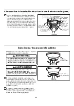
Figura 5
Tornillos (3)
Figura 4
Figura 6
Unidad del motor
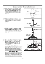
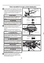
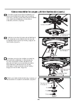
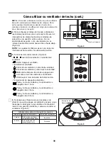
4.
Conecte el cable negro desde ensamble de la
placa del portalámpara al cable negro ensamble
del motor y conecte el cable blanco desde ensamble
de la placa del portalámpara al cable blanco
ensamble del motor. (Figura 4)
5.
Instale la ensamble de la placa del portalámpara
en la unidad del motor utilizando las dos ranuras
principales Colocar el tercera tornillo y asegure los
tres tornillos. (Figura 5)
Ensamble de la placa
de iluminación
Ensamble de la placa
del portalámpara
Ensamble de la placa
del portalámpara
Ensamble de la placa
del portalámpara
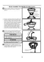
Extraiga uno de los tres tornillos de ensamble
de la placa del portalámpara. Afloje levemente
los otros dos tornillos. Instale ensamble de la
placa de iluminación en la ensamble de la placa
del portalámpara utilizando las dos ranuras
princi-pales. Vuelva a colocar el tercer tornillo y
asegure los tres tornillos. (Figura 6)
6.
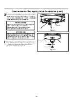
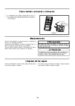
Figura 7
Reborde
7.
Retire el remate del reborde,la tapa y la tuerca, el
del ensamble de la placa de iluminación. (Figura 7)
Tuerca
Tapa
Ensamble de la placa
de iluminación


