background image

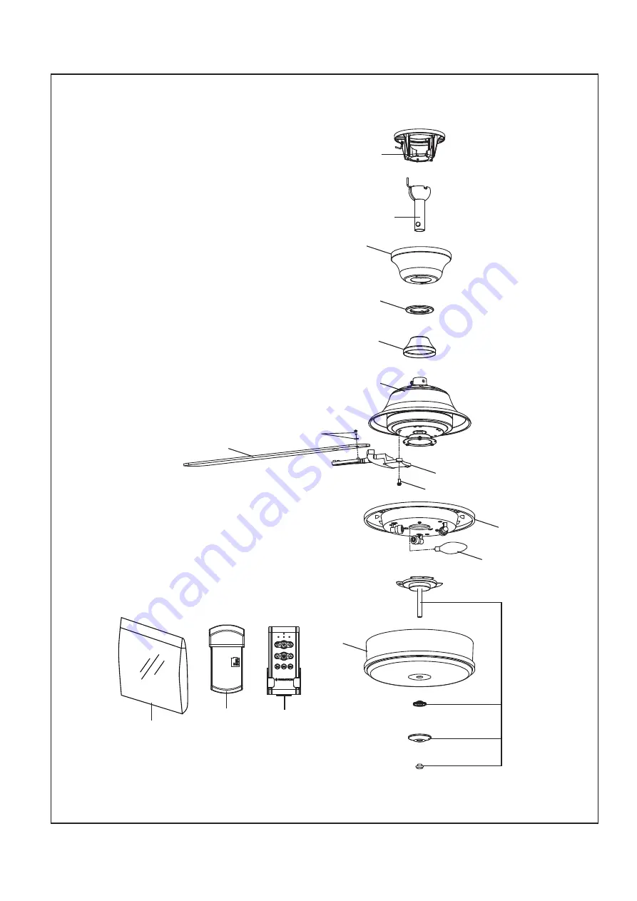
Figura 1

Modelo FP8274** 

Ilustración del despiece

6

11

5

1

3

4

2

8

7

15

15

9

12

10

The Stafford 

42

14

13

15

NOTA: La ilustración que se muestra no está hecha a escala y sucguraciónrealy/oterminación puede variar.

Summary of Contents for STAFFORD FP8274 Series

Page 1: ...10 53 kgs Date Code Purchase Date For best and quickest service please provide date code You can find the date code on the carton hand held remote inside of the battery compartment receiver or top of...

Page 2: ...outlet box marked acceptable for fan support brackets balancing the blades or cleaning the fan Do not insert foreign objects in between rotating fan blades This device complies with Part 15 of the FC...

Page 3: ...Assemble Your Ceiling Fan How to Hang Your Ceiling Fan How to Wire Your Ceiling Fan How to Install Your Canopy Housing 4 5 5 7 9 10 12 How to Assemble the Blades and Light Kit How to Operate Your Ceil...

Page 4: ...der One wire stripper 1 Check to see that you have received the following parts NOTE If you are uncertain of part description refer to exploded view illustration WARNING Do not install or use fan if a...

Page 5: ...5 Amp Circuit Electrical code requires use of a fan rated outlet box to support the extra weight and motion associated with a ceiling fan A fan rated box will be labeled as such and typically supports...

Page 6: ...reduce the risk of fire electrical shock or personal injury mount fan to outlet box marked acceptable for fan support of 15 88 kg 35 lbs or less Use screws supplied with outlet box Most outlet boxes...

Page 7: ...d support is properly installed and the set screws and nuts are securely tightened Failure to do so could result in the fan falling 4 Position downrod support and align the clevis pin holes in both pa...

Page 8: ...ws Route the black white and blue wires and safety cable through the hanger ball Position the pin through the two holes in the downrod and align the hanger ball so the pin is captured in the groove in...

Page 9: ...pply wires including the hanger bracket grounding wire and safety cable are pulled through the downrod between the hanger bracket and the outlet box so that electrical connections can be made later 4...

Page 10: ...remote unit has 32 different code combinations To prevent possible interference from or to other remote units simply change the combination code in the remote and receiver To avoid possible electrical...

Page 11: ...connections are tight including ground and that no bare wire is visible at the wire connectors except for the ground wire Do not operate fan until the blades are in place Noise and motor damage could...

Page 12: ...he blades or cleaning the fan Do not insert foreign objects in between the rotating blades WARNING How to Install Your Canopy Housing 2 Securely attach and tighten the canopy screw cover over the shou...

Page 13: ...ws in the socket plate assembly Slightly loosen the remaining two screws Assemble the light plate assembly to the socket plate assembly using the two key slots in light plate assembly Replace the thir...

Page 14: ...socket plate assembly and secure with nut trim cover and finial Do not overtighten Figure 9 Figure 7 Nut Trim Cover Finial Nut Glass Trim Cover Finial Bulb Figure 8 Figure 9 Light Plate Assembly 14 NO...

Page 15: ...emote control unit 3 To make fan operational install 23A 12V battery included in hand held remote transmitter with fan power off Then follow the remote code setting process If not used for long period...

Page 16: ...ders to motor hub screws are secure and tight Season Summer Winter Rotation Direction Switch Position Clockwise Counterclockwise Reverse Switch Information Right Left 6 If airflow is desired in the op...

Page 17: ...ed off 5 Tighten screws securely 1 Blades not attached to fan 2 Loose screws in motor housing 3 Screws securing fan blade holders to motor flywheel are loose 4 Wire connectors inside housing rattling...

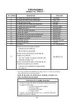
Page 18: ...ADR1 45 Hanger Ball Downrod Assembly 2 PG148 Ceiling Canopy 3 4 Canopy Screw Cover Assembly APPAC1409 Motor Coupling Cover Assembly 5 6 7 AP255BL AP260 8 9 10 11 12 AMA8274F AP827414 AP827405 AP827402...

Page 19: ...274 Exploded View Illustration 1 3 4 2 8 7 15 15 9 12 10 NOTE The illustration shown is not to scale or its actual configuration may vary Product parts are subject to change without notice Figure 1 Th...

Page 20: ...Copyright 2021 Fanimation 2021 04 V 01 10983 Bennett Parkway Zionsville IN 46077 Phone 888 567 2055 Outside U S 317 733 4113 FANIMATION COM FAX 866 482 5215...

Page 21: ...ADJUNTE SU RECIBO AQU Y REGISTRE SU VENTILADOR EN FANIMATION COM LEA Y GUARDE ESTAS INSTRUCCIONES C digo de fecha Fecha de compra Para ofrecer un servicio r pido y de calidad por favor suministre el c...

Page 22: ...utiliza y puede emitir energ a de radiofrecuencia y a menos que se instale y se utilice de acuerdo con el manual de instrucciones puede provocar interferencias perjudiciales en las comunicaciones por...

Page 23: ...durante el transporte Fanimation no se har responsable de los da os que resulten del embalaje incorrecto del producto Se entiende que las reparaciones y las sustituciones son el nico recurso disponibl...

Page 24: ...20 11 Para su comodidad marque cada uno de los pasos Amedida que completa cada paso coloque una marca deveri caci n Con esto se asegurar de completar todos los pasos y podr saber desde d nde retomar s...

Page 25: ...y ahorro de energ a de los ventiladoresdetechodependendesucorrectainstalaci n yuso Acontinuaci nlepresentamosalgunassugerencias para asegurar un rendimiento eficiente del producto Apague el ventilado...

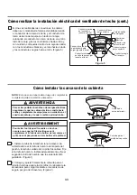
Page 26: ...A fin de evitar incendios o descargas el ctricas siga con cuidado todas las instrucciones de instalaci n el ctrica Cualquier trabajo el ctrico que no se describa en estas instrucciones deber ser real...

Page 27: ...ridad Afloje los dos tornillos de fijaci n del soporte del barral de soporte para techo a trav s de la varilla Lntroduzca los cables de color negro blanco y azu cables y cable de seguridad a trav s de...

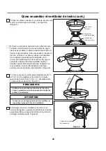
Page 28: ...pasador a trav s de los dos orificios en el barral y alinee la semiesfera de modoque el pasador quede atrapado en la ranura de la partesuperior de la misma Empuje la semiesfera hacia arriba bien ajust...

Page 29: ...t tre solidement ancr e et acceptable pour supporter un ventilateur de 15 9 kg 35 livres au moins Le support de suspension doit reposer fermement contre la bo te de sortie Si la bo te de sortie est en...

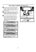
Page 30: ...leng eta en la ranura podr an da arse los cables el ctricos y podr an ocurrir ncendios o descargas el ctricas 4 Levante cuidadosamente el ventilador y coloque el ensamble de la bola para colgar varill...

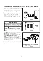
Page 31: ...n a tierra para un funcionamiento seguro Figura 2 Principal Caja De Fusibles Figura 1 Interruptores Receptor Control remoto de mano ON DIP 1 2 3 4 5 Para evitar una posible descarga el ctrica aseg re...

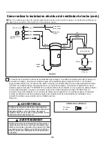
Page 32: ...de la abrazadera para colgar y la varilla al conductor desnudo a tierra con el conector de cables Conecte el conductor negro de la unidad receptora marcado AC IN L al conductor negro de alimentaci n...

Page 33: ...bola para colgar puesta a tierra Conductor blanco del suministro Caja de salida homologada Suministro el ctrico Conductor blanco del receptor Conductor negro del suministro Conductor negro delrecepto...

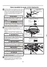
Page 34: ...os dos tornillos y conserve el tornillo retirado Figura 3 Tornillo de cabeza arandela de 3 16 24 y Arandela de fibra Arandela de fibra Aditamentos utilizados x 15 x 15 3 16 24 Tornillo de cabeza de ar...

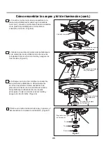
Page 35: ...egure los tres tornillos Figura 5 Ensamble de la placa de iluminaci n Ensamble de la placa del portal mpara Ensamble de la placa del portal mpara Ensamble de la placa del portal mpara Extraiga uno de...

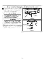
Page 36: ...ns Figura 8 NOTA Si bien es necesario cambiar la l mpara UTILICE S LO M XIMA 4W TIPO E12 DIMMABLE ENUMERADO LED LUZ BOMBILLA C mo ensamblar las aspas y kit de iluminaci n cont RIESGO DE INCENDIOS UTI...

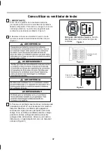
Page 37: ...IA C mo utilizar su ventilador de techo 3 Para que el ventilador sea functional instale las pila incluidas de 23A 12V en el transmisor del mando a distancia Mientras el ventilador est apagado A contin...

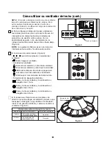
Page 38: ...ol remoto Figura 5 4 Para configurar el c digo del mando a distancia a las mismas posiciones que en el receptor Mueva los interruptores de c digo hasta colocar elc digo de selecci n en la posici n arr...

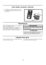
Page 39: ...mejor es utilizar un plumero Mantenimiento El nico mantenimiento necesario para el ventilador de techo es una limpieza peri dica Al llevar a cabo la limpieza use s lo un cepillo suave o un pa o sin p...

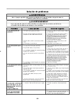
Page 40: ...jos El tornillo de fijaci n en la unidad del barral de la semiesfera est flojo Los tornillos que aseguran los soportes de las aspas al buje del motor est n flojos Los soportes de aspas no est n coloca...

Page 41: ...teriales de embalaje aseg rese de haber extra do todas las piezas Inserte los C DIGOS DE ACABADO consulte el n mero de modelo del ventilador que se encuentra en el soporte de barral C mo hacer un pedi...

Page 42: ...ra 1 Modelo FP8274 Ilustraci n del despiece 6 11 5 1 3 4 2 8 7 15 15 9 12 10 The Stafford 42 14 13 15 NOTA La ilustraci n que se muestra no est hecha a escala y sucguraci nrealy oterminaci n puede var...

Page 43: ...21 Fanimation 2021 04 V 01 Visite nuestro sitio Web en www fanimation com 10983 Bennett Parkway Zionsville IN 46077 Llame sin cargo al 888 567 2055 FAX 866 482 5215 Desde fuera de los EE UU llame al 3...

Reviews: