background image

This manual is sesigned to make it as easy as possible for  you

to assemble, install, operate, and maintain your ceiling fan

Unpacking Instructions

For your convenience, check-of f each step.   As each step is completed, place a check mark.   This will ensure that all 
steps have been completed and will be helpful in f nding your place should you be interrupted. 

Wiring  outlet box and box connectors must be of type 
required by local code.   The minimum wire would be a 3-
conductor (2-wire with ground) of the following size:

NOTE:

  Place the parts from the loose parts bags in a small 

container to keep them from being lost.  If any parts are missing, 
contact your local retailer.

Tools Needed for Assembly

Materials

Wire Size A.W.G.

Installed Wire Length

14
12

Up to 50 ft.

50 - 100 ft.

NOTE:

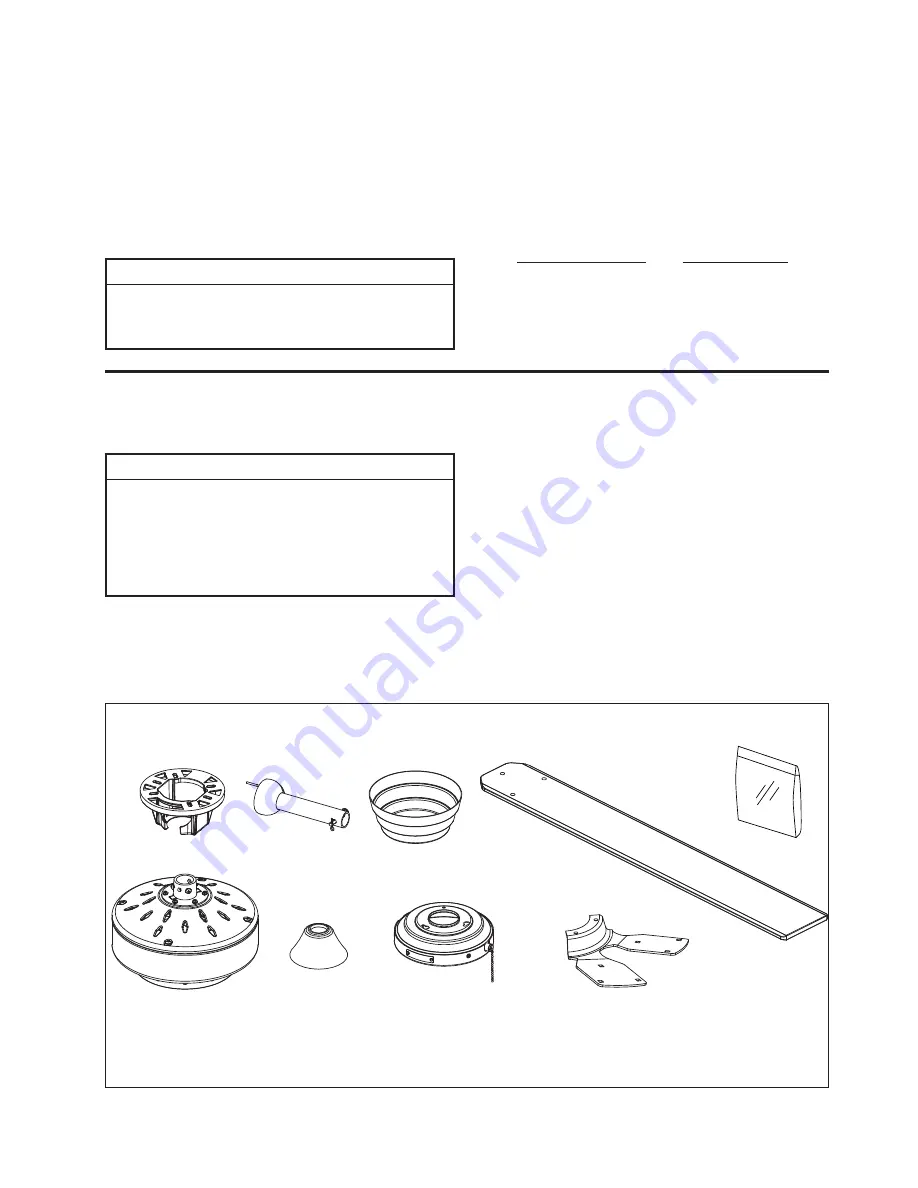
  If you are uncertain of part description, refer to

exploded view illustration. (Figure 1, page 13)

3

1.

Check to see that you have received the following 

parts: 

• Fan Motor Assembly
• Switch Cup/Adapter
  Assembly
• Downrod/Hanger Ball
  Assembly
• Hanger Bracket
• Ceiling Canopy
• Motor Coupling Cover
• Blade Holder Set
• Blade Set

Hardware Bags

Blade Holder Set

Fan Motor Assembly

Downrod/

Hanger Ball

Assembly

Hanger Bracket

• One Phillips head screwdriver
• One stepladder
• One ¼˝ blade screwdriver

• One wire stripper


Three wire connectors

  (supplied)

Ceiling Canopy

Blade Set

• Hardware bags:
   – 1/4˝-20  screws with lockwashers
      (blade holder to fan motor hub) 
     

   – 3/16˝-24 carriage head nut
   – 3/16˝-24 screws & flat washers


      (blade to bladeholder) 
   – Phillips screwdriver, 4˝
   – Two 5/32˝ threaded rods
   – Two 5/32˝ lockwashers
   – Two knurled knobs
   – Ceiling support cable with clamp
   – Flat washer
   – Lag bolt
   – Four wire connectors
   – Chain coupler & chain fob
   – Balance Kit

Motor Coupling Cover

ʆ

WARNING

Do not install or use fan if any part is damaged or 
missing.  This product is designed to use only those 
parts supplied with this product and/or any accessories 
designated specifically for use with this product by 
Fanimation.  Substitution of parts or accessories not 
designated for use with this product by Fanimation could 
result in personal injury or property damage.  Contact 
your retail store for missing or damaged parts.

ʆ

WARNING

Before assembling your ceiling fan, refer to section on 
proper method of wiring your fan (page 9).  If you feel you 
do not have enough wiring knowledge or experience, 
have your fan installed by a licensed electrician.

Switch Cup Housing/

Adapter Assembly

NOTE:

 The illustration shown is not to scale or its 

actual con

¿

 guration or 

¿

 nishes may vary

Summary of Contents for The Levon FP7910 series

Page 1: ...OWNER S MANUAL READ AND SAVE THESE INSTRUCTIONS Model No FP7910 The Levon 8 Bladed Ceiling Fan Net Weight 10 8 kg 23 8 lbs...

Page 2: ...tate to state 10 A certain amount of wobble is normal and should not be considered a problem or a defect LIMITED LIFETIME WARRANTY Extends to the original purchaser of a Fanimation Fan Important Safet...

Page 3: ...wnrod Hanger Ball Assembly Hanger Bracket One Phillips head screwdriver One stepladder One blade screwdriver One wire stripper Three wire connectors supplied Ceiling Canopy Blade Set Hardware bags 1 4...

Page 4: ...updraft which forces warm air near the ceiling down into the occupied space Remember to adjust your thermostat when using your ceiling fan additional energy and dollar savings could be realized with t...

Page 5: ...box with brace Figure 3 Paired with a deep box this hanger is meant to span between two joists and takes the place of wooden blocking To avoid fire or shock follow all wiring instructions carefully A...

Page 6: ...two set screws in the downrod support Route black blue and white lead wires through the downrod Figure 3 4 Position downrod support and align the clevis pin holes in both parts Install the clevis pin...

Page 7: ...pin is captured in the groove in the top of the hanger ball Pull the hanger ball up tight against the pin Securely tighten the set screw in the hanger ball 7 Cut off excess lead wire approximately 6...

Page 8: ...To avoid possible shock do not pinch wires between the downrod hanger ball assembly and the hanger bracket 1 Using the 3 8 x 2 lag bolt and flat washer attach safety cable to ceiling joist or wood str...

Page 9: ...isted Outlet Box Black Green Wire Ground from Hanger Bracket Green Wire Ground Black Fan Wire White Blue Green Wire Ground from Hanger Bowl Figure 1 WARNING To avoid possible electrical shock be sure...

Page 10: ...alled Installing the fan with blades assembled may result in damage to the fan blades WARNING To reduce the risk of personal injury do not bend the blade holders when installing balancing the blades o...

Page 11: ...ith a 4 position 3 speed pull chain switch The operating sequence is as follows 1st Pull HIGH 3rd Pull LOW 2nd Pull MEDIUM 4th Pull OFF Figure 1 Reversing Switch Speed Control Pull Chain Assembling an...

Page 12: ...32 Threaded Rods 2 HDWHW7910 5 32 External Lockwasher 2 Knurled Knobs 2 Blade Balance Kit BALKT Chain Coupler Chain Fob Wire Connectors 4 Blade Mounting Hardware Bag Containing HDWBM7910 3 16 24 Screw...

Page 13: ...13 6 5 7 The Levon FP7910 4 8 1 3 2a 2b 2c 2d 2 NOTE The illustration shown is not to scale or its actual con guration or nishes may vary Figure 1 9 Exploded View Illustration...

Page 14: ...st each other or against the interior wall of the switch housing CAUTION Make sure main power is turned off 5 Some fan motors are sensitive to signals from solid state variable speed controls Solid st...

Page 15: ......

Page 16: ...Copyright 2014 Fanimation 20014 12 V 01 10983 Bennett Parkway Zionsville IN 46077 Toll Free 888 567 2055 FAX 866 482 5215 Outside U S call 317 733 4113 Visit Our Website www fanimation com...

Page 17: ...The Levon 8 aspas Ventilador de techo Peso neto 10 8 kg 23 8 lb MANUAL DEL PROPIETARIO LEA Y GUARDE ESTAS INSTRUCCIONES Modelo N FP7910...

Page 18: ...ectuoso a nuestro centro de servicios nacional Se requiere comprobante de venta El cliente se har responsable de todos los gastos de remoci n o reinstalaci n y env o del producto para reparaciones o s...

Page 19: ...na 29 1 Verifique que haya recibido las siguientes piezas Unidad del motor del ventilador Unidad de la caja del adaptador del interruptor Unidad del barral de la semiesfera Soporte de suspensi n Capuc...

Page 20: ...tinuaci nlepresentamosalgunassugerencias para asegurar un rendimiento eficiente del producto Selecci n del lugar de montaje adecuado Los ventiladores de techo se deben instalar en el centro de la habi...

Page 21: ...a autorizado ADVERTENCIA Apagar el interruptor de pared no es suficiente Para evitar posibles descargas el ctricas aseg rese de que la electricidad est desconectada en la caja de fusibles principal an...

Page 22: ...de horquilla en ambas piezas Instale la clavija de horquilla y aseg rela con la pinza de horquilla Fije los dos tornillos de presi n y las tuercas de seguridad en el soporte de la varilla interior Fig...

Page 23: ...r de la misma Empuje la semiesfera hacia arriba bien ajustada contra el pasador Ajuste firmemente el tornillo de fijaci n en la semiesfera Si el tornillo de fijaci n est flojo podr a provocar oscilaci...

Page 24: ...modo que m s tarde se pueda realizar la instalaci n el ctrica 4 Levante cuidadosamente el ventilador y coloque el ensamble de la bola para colgar varilla en la abrazadera para colgar que acaba de fija...

Page 25: ...talaci n el ctrica NOTA si no est seguro si la caja de distribuci n el ctrica tiene conexi n a tierra pida asesoramiento a un electricista autorizado ya que la conexi n a tierra es importante para un...

Page 26: ...rte de aspas con tuerca de cabeza hexagonal tornillos y arandelas de fibra Aseg rese de que la parte inferior del aspa se encuentre bien apoyada sobre el soporte 4 FIje los tornillos con el destornill...

Page 27: ...e techo Podr a da ar el motor o las aspas y ocasionar posibles descargas el ctricas Limpieza de las aspas Serecomiendalimpiarelpolvodelasaspasperi dicamente Lo mejor es utilizar un plumero Evite usar...

Page 28: ...la pieza N mero de modelo del ventilador P ngase en contacto con su tienda para obtener las piezas de repuesto Antes de desechar los materiales de embalaje aseg rese de haber extra do todas las pieza...

Page 29: ...2b 2c 2d 2 9 29 The Levon FP7910 Figura 1 Producto partes est n sujetas a cambios sin previo aviso NOTA la ilustraci n que se muestra no est hecha a es cala y su con guraci n real puede variar Ilustra...

Page 30: ...alesdeloscontrolesdevelocidaddeestado s lidovariables Loscontrolesde estados lidonoson recomendables Escojaunm todode controlalternativo 6 Ajuste bien los tornillos 7 Asegure bien los tornillos de fi...

Page 31: ......

Page 32: ...Copyright 2014 Fanimation 2014 12 V0 1 10983 Bennett Parkway Zionsville IN 46077 Toll Free 888 567 2055 FAX 866 482 5215 Outside U S call 317 733 4113 Visit Our Website www fanimation com...

Reviews: