background image

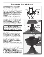
How  to Assemble Your Ceiling Fan

Pin

Setscrew

Hanger

Ball

Figure 1

1. 

Remove  the  Hanger  Ball  by  loosening  the  setscrew 

in  the  Hanger  Ball  until  the  ball  falls  freely  down  the 
Downrod. (Figure 1)  Remove the Pin from the Downrod, 
then remove the Hanger Ball.  Retain the Pin and Hanger 
Ball for reinstallation in Step 5.

2. 

The  fan  comes  with  blue,  black,  white 

80˝

  wires  and 

safety cable. Separate & untwist the three wires and safety 
cable. Route the wires through the downrod.

NOTE: 

 You will be using either the 6

˝

 downrod supplied with 

your fan or an optional downrod purchased separately.

3.

 Loosen the two setscrews in the Downrod Support.  Align 

the Clevis Pin holes in the Downrod with the holes in the 
Downrod Support.  Install the Clevis Pin and secure with 
the Hairpin Clip. (Figure 3)  Be sure to push the straight 
leg of the hairpin clip through the hole near the end of the 
clevis pin until the curved portion of the hairpin clip snaps 
around  the  clevis  pin.   The  hairpin  clip  must  be  properly 
installed to prevent the clevis pin from working loose. Pull 
on  the  Downrod  to  make  sure  the  clevis  pin  is  properly 
installed.

4. 

Route wires and cable through Motor Coupling Cover 

and Canopy on fan shown with open side facing up. 
(Figure 3)

5. 

Reinstall  the  Hanger  Ball  (Figure  1)  on  the  Downrod 

as follows.  Route the three 

80˝

 wires and cable through 

the  Hanger  Ball.  Position  the  Pin  through  the  two  holes 
in  the  Downrod  and  align  the  Hanger  Ball  so  the  Pin  is 
captured in the groove in the top of the Hanger Ball.  Pull 
the Hanger Ball up tight against the pin. 

Securely tighten 

the  setscrew  in  the  Hanger  Ball.    A  loose  setscrew 

could create fan wobble.

6. 

While pulling up on the hanger ball, securely tighten the 

two 3/16-24 x 

3/8˝

 setscrews in the downrod support. Slide 

the Motor Coupling Cover down. (Figures 2 & 3)

7. 

The fan comes with blue, black, white leads and support 

cable.  Before  installing  fan,  measure  up  approximately 
6-9 inches above top of Downrod/Hanger Ball Assembly.  
Cut off excess wire and strip back insulation 

½˝

 from end 

of wire.

8. 

All set screws must be checked and retightened where 

necessary before installation.

9.

 You  have  now  completed  the  upper  assembly  of  your 

new  ceiling  fan.   You  can  now  proceed  with  the  hanging 
and the electrical wiring of your fan.

Hairpin Clip

Setscrew (2)

Motor

Coupling

Cover

Figure 2

Figure 3

Clevis Pin

Downrod 

Support

WARNING

It  is  critical  that  the  clevis  pin  in  the  downrod  support 

is  properly  installed  and  the  setscrews  are  securely 

tightened.  Failure to verify that the pin and setscrews 

are properly installed could result in the fan falling.

5

Summary of Contents for The Levon FP7910BN

Page 1: ...OWNER S MANUAL READ AND SAVE THESE INSTRUCTIONS Model No FP7910OB The Levon 8 Bladed Ceiling Fan Net Weight 10 8 kg 23 8 lbs...

Page 2: ...t vary from state to state 10 A certain amount of wobble is normal and should not be considered a problem or a defect LIMITED LIFETIME WARRANTY Extends to the original purchaser of a Fanimation Fan Im...

Page 3: ...er Ball Assembly Hanger Bracket One Phillips head screwdriver One stepladder One blade screwdriver One wire stripper Three wire connectors supplied Ceiling Canopy Blades Hardware bags 20 x 14mm blade...

Page 4: ...need to be replaced Consult a qualified electrician if in doubt Energy Efficient Use of Ceiling Fans Ceiling fan performance and energy savings rely heavily on the proper installation and use of the c...

Page 5: ...wn with open side facing up Figure 3 5 Reinstall the Hanger Ball Figure 1 on the Downrod as follows Route the three 80 wires and cable through the Hanger Ball Position the Pin through the two holes in...

Page 6: ...o avoid possible shock do not pinch wires between the downrod hanger ball assembly and the hanger bracket 1 Using the 3 8 x 2 lag bolt and flat washer attach safety cable to ceiling joist or wood stru...

Page 7: ...isted Outlet Box Black Green Wire Ground from Hanger Bracket Green Wire Ground Black Fan Wire White Blue Green Wire Ground from Hanger Bowl Figure 1 WARNING To avoid possible electrical shock be sure...

Page 8: ...the motor hub are tight and that the blade holders are properly seated Housing Switch Cup Adapter Assembly 7 Disassemble the Housing Switch Cup Adapter assembly by removing three screws Figure 4 8 Ass...

Page 9: ...ntly pulling on the pull chain switch Figure 1 3 If airflow is desired in the opposite direction turn the fan off and wait for the blades to stop turning Then slide the reverse switch to the opposite...

Page 10: ...o H e d a l B 7 L W 3 0 0 0 8 8 P A 8 e d a l B 8 9 Hardware Bag Containing HDWFP7910SS 5 32 Threaded Rods 2 HDWHW7910SS 5 32 External Lockwasher 2 Knurled Knobs 2 Blade Balance Kit BALKT Chain Couple...

Page 11: ...11 6 5 7 The Levon FP7910OB Exploded View 4 8 1 3 2a 2b 2c 2d 2 NOTE The illustration shown is not to scale or its actual configuration or finishes may vary Figure 1 9...

Page 12: ...other or against the interior wall of the switch housing CAUTION Make sure main power is turned off 5 Some fan motors are sensitive to signals from solid state variable speed controls Solid state con...

Page 13: ......

Page 14: ...Copyright 2011 Fanimation 20011 08 V 01 10983 Bennett Parkw ay Zionsville IN 46077 Toll Free 888 567 2055 FAX 866 482 5215 Outside U S call 317 733 4113 Visit Our Website w w w fanimation com...

Page 15: ...The Levon 8 aspas Ventilador de techo Peso neto 10 8 kg 23 8 lb MANUAL DEL PROPIETARIO LEA Y GUARDE ESTAS INSTRUCCIONES Modelo N FP7910OB...

Page 16: ...ctuoso a nuestro centro de servicios nacional Se requiere comprobante de venta El cliente se har responsable de todos los gastos de remoci n o reinstalaci n y env o del producto para reparaciones o su...

Page 17: ...tilador Para su comodidad marque cada uno de los pasos Amedida que completa cada paso coloque una marca de veri caci n Con esto se asegurar de completar todos los pasos y podr saber desde d nde retoma...

Page 18: ...l ventilador de techo a velocidad baja y en el sentido de las agujas del reloj Esto produce una suave corriente ascendente que obliga al aire c lido que se acumula cerca del techo a bajar al espacio o...

Page 19: ...las tuercas est n bien ajustados Si el tornillo Clevis las tuercas el pasador de horquilla y los tornillos de fijaci n no est n correctamente colocados el ventilador podr a caerse ADVERTENCIA 5 Vuelva...

Page 20: ...modo que m s tarde se pueda realizar la instalaci n el ctrica 4 Levante cuidadosamente el ventilador y coloque el ensamble de la bola para colgar varilla en la abrazadera para colgar que acaba de fija...

Page 21: ...laci n el ctrica NOTA si no est seguro si la caja de distribuci n el ctrica tiene conexi n a tierra pida asesoramiento a un electricista autorizado ya que la conexi n a tierra es importante para un fu...

Page 22: ...rriba 3 Ensamble el aspa en el soporte de aspas con tuerca de cabeza hexagonal tornillos y arandelas de fibra Aseg rese de que la parte inferior del aspa se encuentre bien apoyada sobre el soporte 4 F...

Page 23: ...nversor a la posici n contraria y vuelva a encender el ventilador Su modelo de ventilador est equipado con un interruptor de cadena de 4 posiciones y 3 velocidades La secuencia de funcionamiento es la...

Page 24: ...a pieza N mero de modelo del ventilador P ngase en contacto con su tienda para obtener las piezas de repuesto Antes de desechar los materiales de embalaje aseg rese de haber extra do todas las piezas...

Page 25: ...he Levon FP7910OB 4 8 1 3 2a 2b 2c 2d 2 Figura 1 9 Despiece Producto partes est n sujetas a cambios sin previo aviso NOTA la ilustraci n que se muestra no est hecha a escala y su con guraci n real pue...

Page 26: ...s controles de velocidad de estado s lido variables Los controles de estado s lido no son recomendables Escoja un m todo de control alternativo 6 Ajuste bien los tornillos 7 Asegure bien los tornillos...

Page 27: ......

Page 28: ...Copyright 2011 Fanimation 2011 08 V0 1 10983 Bennett Parkw ay Zionsville IN 46077 Toll Free 888 567 2055 FAX 866 482 5215 Outside U S call 317 733 4113 Visit Our Website w w w fanimation com...

Reviews: