7
SECTION 3
SPRING CALIBRATION PROCEDURE
MODEL 280 RHEOMETER
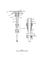
This procedure requires the removal of the Torsion Shaft Assembly, shown in Fig.1, from the
Rheometer, and mounting it in the Calibration Fixture.
A.
Torsion Shaft Assembly Removal
1.
Unscrew and remove the Sleeve, Bob, and Dust Shield from the Rheometer.
2.
Place Rheometer speed shift lever in 300 RPM speed setting.
3.
Remove flat head screw from center of Gel Knob.
4.
Holding Gel Knob loosen hex set screw 1/4 turn using a hex key wrench and, then
unscrew and remove Gel Knob.
5.
Move Speed shift lever to the STIR position and pull shift arm, cam, and bearing
off shift rod.
6.
While holding rotor from turning, turn crank backward thereby unscrewing and
removing it.
7.
Remove four 6-32 x 1/4 long screws holding cover to frame, then pull cover up and
off Rheometer.
8.
Remove flat head screw [79] from top center of dial, then carefully lift dial straight
up and remove.
9.
Loosen two Zeroing screws that act as set screws against the flat on the Torsion
Body, sufficiently to clear and allow removal of the torsion body.
10.
Remove the large retainer ring on top of the Torsion Body.
11.
Lift the torsion shaft assembly up and out of the Rheometer frame.
12.
Re-assemble the Dial [60] onto the top of the Bob Shaft and secure it with screw
[79].
B.
Preliminary Spring Setting
A preliminary setting of the torsion spring should be made prior to mounting it in the fixture.
Make this setting as follows:
1.
Set the torsion spring assembly for approximately 9-1/4 to 9-1/2 pair turns by
rotating the outer collet [67-3]. (Refer to Fig. 1) on spring [67] to the proper point.
2.
Grasp the flats on lock collet [64] with needle nose pliers between lower spring
coils. Holding the dial [60] turn it, torsion shaft, and collet [65] clockwise to loosen
the thin notched portion of lock collet [64] from the spring [67]. and collet 67-3].
3.
Slide the spring, with the outer collet [67-3] on it, over lock collet [64] until top of
collet [67-3] is approximately even with top of lock bushing [65].
Summary of Contents for 280
Page 5: ...2 ...
Page 8: ...5 Fig 1 Typical Torsion Shaft Assembly ...
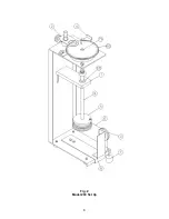
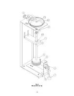
Page 9: ...6 Fig 2 Model 280 Set Up ...
Page 13: ...10 Fig 3 Model 286 Set Up ...

