13
D.
Taking the Readings
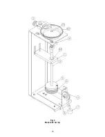
Hang the 25, 50 and 75 Gram weights each in turn on the loop in the end if the thread and
note the dial readings obtained. (Refer to Table 1). If the dial readings are higher than
shown in Table 1 - shorten the active part of the spring. If the dial readings are lower than
shown in Table 1 - lengthen the active part of the spring.
E.
Adjusting Torsion Spring:
1.
Loosen hex set screw [81-B] holding upper spring collet [67-2] in torsion assembly
body [61].
2.
Loosen torsion spring adjusting collet as described in Section 3B-2. If the readings
were too high, screw the threaded outer collet [67-3] up the spring pairs (1/4 turn
will drop 3-5 dial units). If the readings were too low, screw the threaded outer
collet [67-3] down the spring pairs (1/4 turn will change reading 3-5 dial units).
3.
Align top of outer collet [67] slightly above top of widest section of lock bushing
[65]. Tighten torsion spring adjusting collet as described in Section 3B-4.
4.
Push upper spring collet [67-2] into torsion assembly body [61] and lock it with hex
set screw [81-B] in a position so that dial zero aligns with the hairline.
5.
Check calibration as described in Section 3D above. If still incorrect, repeat this
section.
F.
Re-assembly of the Torsion Shaft Assembly into the Rheometer.
1.
Loosen and rotate the hairline/magnifier out of the way of removing the Torsion
Shaft Assembly.
2.
Unscrew the Calibration spool [5] and the thread [6] and remove them.
3.
Remove screw [79], then remove dial [60].
4.
Loosen and remove the lock bar [4] holding the Torsion Body, then lift the Torsion
Body out of the Calibration Fixture.
5.
Place the Torsion Shaft Assembly in the Rheometer with the flat on the Torsion
Body toward the right side of the Rheometer, then install the retainer on top of the
Torsion Body.
6.
Reposition the printed circuit board on the top of the Rheometer. Be especially
careful to make sure the following are not damaged.
Make sure the encoder disc on the motor flywheel fits into the groove of the
photo transistor sensor assembly.
DO NOT BEND THIS DISC.
Make sure the heat sink surfaces
on the power transistor and the voltage
regulator and the corresponding surfaces of the frame have been cleaned
and new heat sink compound has been applied.
Summary of Contents for 280
Page 5: ...2 ...
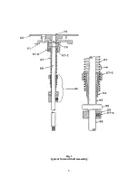
Page 8: ...5 Fig 1 Typical Torsion Shaft Assembly ...
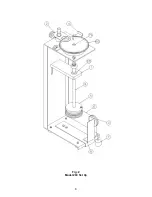
Page 9: ...6 Fig 2 Model 280 Set Up ...
Page 13: ...10 Fig 3 Model 286 Set Up ...

