background image


14 


Make sure all holes in the circuit board are in line and nothing is binding the 
circuit board as it is assembled into place.   


Make  sure  the  two  top  mounting  holes  are  in  line  and  the  holes  for  the 
power transistor and voltage regulator are in line. 


7. 

Mount the circuit board by installing the following screws: 


Two screws from the top of the PC board into the frame 


One screw holding the power transistor to the frame   


One screw holding the voltage regulator to the frame   


8. 

Assemble the dial [60] and secure with screw [79].  


9. 

Temporally  place  the  cover,  with  the  hairline  jewel  in  it, in place and observe the 
position of the hairline with relation to the "0" on the dial.  


Remove the cover and adjust the two zeroing screws on the right side of the frame 
and  against  the  flat  on  the  Torsion  Body.  Loosen  one  and  tighten  the  other  to 
slightly rotate the torsion body as needed to align the "0" with the hairline.   


Recheck using the cover and repeat if necessary.  Both zero adjust screws should 
be tight against the torsion body when adjustment is complete.   


10. 

Install Cover be installing the following fasteners:  


Two 6-32 x 1/4 long cover to frame screws 


Two 6-32 x 1/4 long cover to power supply bracket screws.  


Nut cover to speed selector switch  


Nut cover to variable speed potentiometer.   (Use socket wrenches or nut 
drivers). 


11. 

Install  switches.  Use  hex  key  wrenches  to  tighten  their  set  screws.  Make  sure 
these set screws are seated on the flats on the switch shafts. 


Power ON/OFF switch 


Speed selector switch knob  


Variable speed control     


12.  

Assemble the Dust Shield and the Bob onto the Bob Shaft, then screw the Sleeve 
onto the Rotor.          


13. 

Connect the Model 286 Rheometer to the power source and test its performance.  


NOTE: This  spring  calibration  should  be  verified  after  assembly  of 

Rheometer  by  the  silicone  oil  calibration  method.    Refer  to 
Model 286 Instructions.  

Summary of Contents for 280

Page 1: ...Rheometer Calibration Fixture Instruction Manual Model 280 286 Instruction Manual Part No 204210 Revision B ...

Page 2: ...l without first receiving the written permission of Fann Instrument Company Houston Texas U S A Printed in U S A NOTE Fann reserves the right to make improvements in design construction and appearance of our products without prior notice FANN is a registered trademark of Fann Instrument Company Fann Instrument Company P O Box 4350 HOUSTON TEXAS U S A 77210 TELEPHONE 281 871 4482 TOLL FREE 800 347 ...

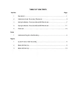
Page 3: ...cedure Rheometer 3 3 Spring Calibration Procedure Model 280 Rheometer 7 4 Spring Calibration Procedure Model 286 Rheometer 11 5 Parts List 15 Table 1 Calibration Weight vs Dial Reading 4 Figure 1 Typical Torsion Shaft Assembly 5 2 Model 280 Set Up 6 3 Model 286 Set Up 10 ...

Page 4: ...ng the active length of the spring The Calibration Fixture may be used for Calibration of a replacement spring when it is being installed Verification of the calibration of the spring already in the instrument Re calibration of the spring already in the instrument Check the following parts of the Rheometer for runout or damage If any of these parts are bent or otherwise damaged repairs must be mad...

Page 5: ...2 ...

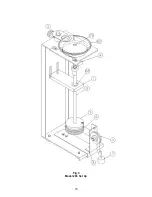
Page 6: ...e hole in the Pulley Support closest to the pulley for the Model 280 Rheometer and away from the pulley for the Model 286 Rheometer 4 Screw Calibration spool 5 onto bob shaft threads down until it tight Wind two to three turns of thread around the drum clockwise as viewed from the top of the spool Refer to Fig 2 for Model 280 and Fig 3 for Model 286 Route the thread over the sheave and allow it to...

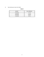
Page 7: ...4 B Take readings as shown in the Table 1 TABLE 1 WEIGHT DIAL READING 25 GRAMS 103 104 50 GRAMS 204 206 75 GRAMS 309 312 ...

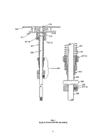
Page 8: ...5 Fig 1 Typical Torsion Shaft Assembly ...

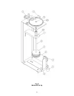
Page 9: ...6 Fig 2 Model 280 Set Up ...

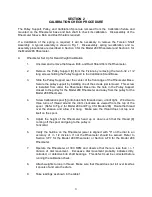
Page 10: ... straight up and remove 9 Loosen two Zeroing screws that act as set screws against the flat on the Torsion Body sufficiently to clear and allow removal of the torsion body 10 Remove the large retainer ring on top of the Torsion Body 11 Lift the torsion shaft assembly up and out of the Rheometer frame 12 Re assemble the Dial 60 onto the top of the Bob Shaft and secure it with screw 79 B Preliminary...

Page 11: ...s with the divisions on the dial and lock in place Loosen set screw 81 B to loosen collet 67 2 in the torsion body 61 then rotate the dial and bob shaft to align Zero with the hairline Lock collet 67 2 in this position with set screw 81 B 6 Screw Calibration spool 5 onto bob shaft threads down until it is tight Wind two to three turns of thread around the drum clockwise as viewed from the top of t...

Page 12: ...nst the flat on the torsion body to slightly rotate the torsion body as needed to align the 0 with the hairline Recheck using the cover and repeat if necessary Both zero adjust screws should be tight against the torsion body 8 Place cover in place and install the four 6 32 x 1 4 long cover to frame screws 9 Position shift arm in the STIR position then install the shift arm cam and bearing onto the...

Page 13: ...10 Fig 3 Model 286 Set Up ...

Page 14: ... the cover up and off Rheometer 9 Remove flat head screw 79 from top center of dial 60 then carefully lift dial straight up and remove 10 Remove printed circuit board by removing screws as follows Two 4 40 screws mounting the printed circuit board to the frame These two screws go through the circuit board from the top One is near each side of the board about 5 inches 12 7 cm from the square end On...

Page 15: ...sion shaft assembly Refer to Fig 3 1 Install the pulley 3 into the bottom hole of the pulley holder bracket 2 Loosen the two screws holding the lower bearing support bar 1 and position it at the bottom of the slots and re tighten the screws 3 Slide torsion shaft assembly into fixture from the top Position torsion body hub into the hole in the top of the fixture and bearing 68 in the hole in the lo...

Page 16: ... 61 and lock it with hex set screw 81 B in a position so that dial zero aligns with the hairline 5 Check calibration as described in Section 3D above If still incorrect repeat this section F Re assembly of the Torsion Shaft Assembly into the Rheometer 1 Loosen and rotate the hairline magnifier out of the way of removing the Torsion Shaft Assembly 2 Unscrew the Calibration spool 5 and the thread 6 ...

Page 17: ...to slightly rotate the torsion body as needed to align the 0 with the hairline Recheck using the cover and repeat if necessary Both zero adjust screws should be tight against the torsion body when adjustment is complete 10 Install Cover be installing the following fasteners Two 6 32 x 1 4 long cover to frame screws Two 6 32 x 1 4 long cover to power supply bracket screws Nut cover to speed selecto...

Page 18: ...grams 207849 Thread 204210 Instructions 205683 Bearing bob shaft B Optional Calibration Fluids PART NO DESCRIPTION 207124 Calibration Fluid 10 cP 207119 Calibration Fluid 20 cP 207120 Calibration Fluid 50 cP 207121 Calibration Fluid 100 cP 207122 Calibration Fluid 200 cP 207123 Calibration Fluid 500 cP ...

Page 19: ...inst possible damage or loss Fann will not be responsible for damage resulting from careless or insufficient packing Out of warranty products will be repaired for a nominal charge Return of Items Before returning items for any reason authorization must be obtained from Fann Instrument Company When applying for authorization please include information regarding the reason the items are to be return...

Reviews: