3
SECTION 2
CALIBRATION CHECK PROCEDURE
The Pulley Support, Pulley, and Calibration Spool are removed from the Calibration fixture and
mounted on the Rheometer base and bob shaft to check its calibration. Dis-assembly of the
Rheometer Sleeve, Bob, and Dust Shield is required.
If a Calibration of the spring is required, it will be necessary to remove the Torsion Shaft
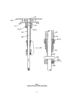
Assembly. A typical assembly is shown in Fig. 1. Dis-assembly, spring re-calibration, and re-
assembly procedures are described in Section 3 for the Model 280 Rheometer and Section 4 for
the Model 286 Rheometer.
A.
Rheometer Set Up for Dead Weight Calibration
1.
Unscrew and remove the Sleeve, Bob, and Dust Shield from the Rheometer.
2.
Remove the Pulley Support [8] from the Fixture by removing the two 6-32 x 1/2
long screws holding the Pulley Support to the Calibration Stand Base.
3.
Slide the Pulley Support over the center of the front edge of the Rheometer Base.
Secure the pulley support by installing one of the screws just removed. This screw
is installed from under the Rheometer Base into the hole in the Pulley Support
closest to the pulley for the Model 280 Rheometer and away from the pulley for the
Model 286 Rheometer.
4.
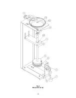
Screw Calibration spool [5] onto bob shaft, threads down, until it tight. Wind two to
three turns of thread around the drum clockwise as viewed from the top of the
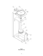
spool. (Refer to Fig. 2 for Model 280 and Fig. 3 for Model 286) Route the thread
over the sheave, and allow it to hang. Make sure the thread does not lap over
itself on the spool.
5.
Adjust the height of the Rheometer head up or down such that the thread [6]
coming off the spool and going to the pulley is
horizontal.
6.
Verify the hairline on the Rheometer jewel is aligned with "0" on the dial to an
accuracy of +/- 1/2 division. If not the Rheometer should be zeroed. Refer to
Section 3-F7 for the Model 280 Rheometer or Section 4-F9 for the Model 286
Rheometer.
7.
Operate the Rheometer at 300 RPM and observe that there is less than +/- 1
division of dial movement. Excessive dial movement probably indicates dirty,
corroded, or defective bob shaft bearings. This defect must be corrected before
running the calibration check.
8.
Attach weights to loop in thread. Make sure that thread does not roll over itself as
it spools of and onto the drum.
9.
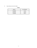
Take readings as shown in the table 1.
Summary of Contents for 280
Page 5: ...2 ...
Page 8: ...5 Fig 1 Typical Torsion Shaft Assembly ...
Page 9: ...6 Fig 2 Model 280 Set Up ...
Page 13: ...10 Fig 3 Model 286 Set Up ...

