Rev.23
273/311
10.
IEC 61850 PROTOCOL
This section describes the implementation of IEC 61850 protocol.
IEC 61850 protocol defines a way of structuring the available information in each device,
that is reflected in the Data Model and a way of managing and sending this information
through communications using specific Services.
SILB device will be known as a Server IED (Intelligent Electronic Device), which services
will be available using the Ethernet through its default IP (192.168.0.121)
MMS will be the used Ethernet protocol for the Client-Server communication and 102 will be
the used port.
GOOSE fast messages is not a Client-Server communication like TCP/IP but a Multicast
communication that sends messages directly to the Link Layer using MAC directions as
destination directions for publishing the GOOSE.
10.1. Data model
Server IEDs have all the information of all their events, measures, parameters and services,
organized in a hierachical structure
with device’s functional units as main ones.
The main level of the structure is the name of the IED, by default TEMPLATE, with its
instance LD1
Down the IED there are Logical Nodes that represent the functional units of the IED
(Protection, Control and measure units, status of external elements like circuit breaker, etc.)
Inside Logical Nodes there are Data objects that compose a functional unit, and inside each
Data object, there are Data attributes that give complete information about this Data object.
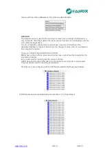
As example, the ground overcurrent protection unit is represented in SILB according IEC
61850 as the logical node PIOC, with the prefix GND and the instance 1: GNDPIOC1
In the Logical Node, the starting of the unit is represented by its Data Object,
Str
, with a list
of Data Attributes that give information about the starting:
Attribute
neut
indicates the status of the starting,
t
attribute indicates the time stamp when
the starting has changed, etc.
Summary of Contents for SIL B
Page 1: ...EN_FANOXTD_MANU_SIL_Feeder_SILB_R023 Docx USER S MANUAL SIL B Feeder Relay...
Page 8: ...www fanox com Rev 23 8 311 2 DIMENSIONS AND CONNECTION DIAGRAMS 2 1 Equipment front view...
Page 9: ...www fanox com Rev 23 9 311 2 2 Equipment dimensions...
Page 10: ...www fanox com Rev 23 10 311...
Page 11: ...www fanox com Rev 23 11 311 2 3 Cut out pattern CUT OUT PATTERN...
Page 12: ...www fanox com Rev 23 12 311 2 4 Connection diagrams Analog connections...
Page 13: ...www fanox com Rev 23 13 311...
Page 14: ...www fanox com Rev 23 14 311 Digital connections Outputs and Trip circuit supervision...
Page 15: ...www fanox com Rev 23 15 311 2 5 Terminals IEC 61850 or DNP3 0 protocols...
Page 17: ...www fanox com Rev 23 17 311 IEC 60870 5 103 protocol...
Page 25: ...www fanox com Rev 23 25 311 3 3 Functional diagram...
Page 28: ...www fanox com Rev 23 28 311 3 5 1 SIL B 1 CHARGE CURVE 3 5 2 SIL B 5 CHARGE CURVE...
Page 91: ...www fanox com Rev 23 91 311...
Page 140: ...www fanox com Rev 23 140 311...
Page 194: ...www fanox com Rev 23 194 311 Polarization V 35 0 V C Operating Angle 180 C Halfcone Angle 3 C...
Page 307: ...www fanox com Rev 23 307 311 50BF init Fault init 79 Closure permission 52 closure permission...
Page 310: ...www fanox com Rev 23 310 311 NOTES...
Page 311: ...www fanox com Rev 23 311 311...


