background image

OWNERS INSTRUCTION

MANUAL

INSTALLATION

OPERATION

 MAINTENANCE

102CM/40”

Cirrus

CAUTION

READ INSTRUCTIONS CAREFULLY FOR SAFE   

INSTALLATION AND FAN OPERATION. IF UNSURE CONSULT

A QUALIFIED ELECTRICIAN

SUITABLE FOR 230V/50 CYCLE ELECTRICAL SUPPLY

Enquiries on installing your fan please call our help line on

01959-564440

E-mail :

             technical@fantasiaceilingfans.com

Summary of Contents for Elite Cirrus

Page 1: ...CAUTION READ INSTRUCTIONS CAREFULLY FOR SAFE INSTALLATION AND FAN OPERATION IF UNSURE CONSULT A QUALIFIED ELECTRICIAN SUITABLE FOR 230V 50 CYCLE ELECTRICAL SUPPLY Enquiries on installing your fan please call our help line on 01959 564440 E mail technical fantasiaceilingfans com ...

Page 2: ......

Page 3: ...e able to support the moving weight of the fan and must not twist or work loose The fan must be earthed Do not connect the fan motor to a dimmer switch This may give an unsatisfactory performance motor hum and cause damage to the motor It is not recommended that ceiling fans and gas appliances are operated in the same room at the same time The fan must be turned off and stopped completely before r...

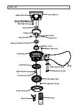
Page 4: ...py Split Pin Boss Cover Canopy Screw Cotter Pin Fan Motor Light Plate Light Plate Screw Push Connector Glass shade LED Light Fitter blade support plate Round Steel Washer Spring Steel Washer Joist of Beam Blade Light Fitter Screw Handset Receiver Blade Set Screw Blade Set Screw ...

Page 5: ... a firm flat surface The fixing location must be able to withstand ten times the static weight of the fan If you have any doubts as to the ability of your intended fixing location to be able to withstand this loading Please contact our service help line or another competent authority to advise you In most situation two wood screws screwed into a wooden joist is more than adequate to support your c...

Page 6: ... recess When aligned the fan should drop slightly as it assumes it s correct position This is to prevent rotation of the rod and fan when the unit is working REFER TO THE WIRING INSTRUCTIONS NEXT Carefully lift the fan motor assembly up to the hanger bracket and seat the hanger ball downrod assembly in the mounting bracket socket Loosen the drop rod set screws on the boss which is on top of the mo...

Page 7: ...E is connected to L BROWN wire BLUE BLACK wire is NEUTRAL is connected to N BLUE wire GREEN YELLOW wire is EARTH Connect the 4 lead wires coming from the fan housing with 4 wires coming from the other side of the remote control receiver where indicated sticker with brown blue orange block BROWN TO BROWN Live wire of fan BLUE TO BLUE Neutral wire of fan ORANGE TO ORANGE Live wire of light GRN YEL T...

Page 8: ...acket Turn the canopy clockwise until the canopy locks in place at the narrow section of the key holes Align the circular hole on the canopy with the remaining hole on the mounting bracket Secure the canopy mounting screw previously removed in the hole and tighten the two canopy mounting screw Attach the canopy bottom cover to the canopy by inserting the canopy mounting screw into the key slots in...

Page 9: ...w Secure fan upper section with the screw previously removed through the motor window Align three holes on blade support plate with three holes on blade lower section and on blade arm and secure with three blade lower section attachment screws with lock washers provided Repeat this procedure for remaining blades Re install the decorative cover back to the fan motor housing by using the two decorat...

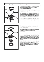
Page 10: ...the three light kit mounting screws from the light kit mounting plate and loosen the other two screws Do not remove While holding the 18W LED light kit under the fan motor assembly make the 2 pin wire connections White to white Black to black Place the key holes in the 18W LED light kit over the two mounting screws previously loosened from the light kit mounting plate Turn the 18W LED light kit un...

Page 11: ...the timer by pressing button and re start the fan speed NOTE The distance between the transmitter and receiver should not be greater than 30 feet For best performance make sure the Black Antenna on the end of the receiver unit remains extended and not tangled with any of the electrical wires Remote pairing process NOTE This unit is equipped with an automatically learning type remote control There ...

Page 12: ...r This may be due to slight irregularities in the blades or blade carriers Deviating from these instructions can cause further problems The following procedure may help to rectify the situation The hanging bracket must always be tight against the ceiling so that no movement can occur Make sure that the rod is firmly locked into the boss on top of the fan The locking screw should be securely tighte...

Page 13: ...pting to repair the fan Ceiling Fan Warranty You must have the original purchase receipt or bill of sale to make a warranty claim No claim will be accepted unless proof of date of purchase is available at the time of making the warranty claim Ceiling Fan Warranty Period The ceiling fan itself excluding accessories such as the Remote Control Transmitter and Receiver is covered by a 10 year warranty...

Page 14: ...40 102cm Cirrus FANTASIA DISTRIBUTION LTD Unit B The Flyers Way Westerham Kent TN16 1DE Tel 01959 564 440 Fax 01959 564 829 E MAIL info fantasiaceilingfans com ...

Page 15: ......

Page 16: ...gfans com and fill in the warranty section there Please cut out this warranty page and send it in an envelope to the address below FANTASIA DISTRIBUTION LTD Unit B The Flyers Way Westerham Kent TN16 1DE Tel 01959 564 440 Fax 01959 564 829 E MAIL info fantasiaceilingfans com ...

Reviews: