9
INTERIOR DUCTING INSTALLATION
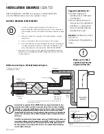
• To maximize airflow through the ductwork system, all ducts should be kept short and have as few bends or elbows as possible.
• 45º elbows are preferable to 90º.
• Use “Y“ ducts instead of “T” ducts whenever possible.
• All duct joints must be fastened with screws or duct sealant and wrapped with aluminum foil duct tape to prevent leakage.
• Galvanized ducting from the FAA to the living areas in the house is recommended whenever possible, although flexible ducting
can be used in moderation when necessary.
• To avoid possible noise transfer through the ductwork system, a short length (approximately 300 mm, 12’’) of nonmetallic flexible
insulated duct should be connected between the FAA and the supply/exhaust ductwork system.
• The main supply and return line to/from the FAA must have the same diameter as the duct connection or larger.
• Branch lines to the individual rooms may be as small as 100 mm (4’’).
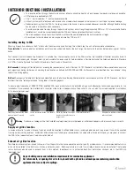
Installing ducting to FAA
Warning: Always fix and secure the 6" collars with the screws supplied. Avoiding this critical step the unit will accumulate condensation.
Tip to Installer:
To ensure a better installation and to avoid an undesired bend in the duct, align the duct with the collar before securing over the four
hooks.
The fresh air from outside and the Exhaust air to outside from the termination ducts to the FAA must be fully insulated of thermal insulation ducts to
minimize heat loss and gain. All tapes, mastics, and nonmetallic clamps used for field installation of flexible ducts shall be listed and labeled to Standard
UL 181B - Closure Systems for Use With Flexible Air Ducts and Air Connectors.
Air Connector
A category of flexible duct not meeting the requirements of an Air Duct per UL 181 Standard (not tested for flame penetration, puncture
and impact) and having limitations on use, length and location as defined by NFPA 90A and 90B. Air Connectors are identified by a “round shape” listing
label of the listing agency.
Air Duct
A category of flexible duct tested and classified as to the Surface Burning Characteristics in accordance with the UL 181 Standard. Air Ducts
are identified by a “rectangular shape” listing label of the listing agency.
To ensure quiet operation of ENERGY STAR qualified FAA, each product should be installed using sound attenuation techniques appropriate for the
installation. Once insulated flex is attached to the collar, slide collar in keeper section, fixed collar to the unit with four screws supplied in installation
kit to insure a proper seal.
Warning
: To reduce air leakage in the final installation always seal the joint between all collars and keepers with aluminum tape or mastic.
Supply air grilles location
In homes without a forced air furnace, fresh air should be supplied to all habitable rooms, including bedrooms and living areas. It should be supplied
from high wall or ceiling locations. Grilles that diffuse the air comfortably are recommended. In homes with a forced air furnace, you may want to connect
the FAA to the furnace ductwork (see information below).
Exhaust air grilles location
The stale air exhaust system is used to draw air from the points in the house where the worst air quality problems occur. It is recommended that return
air ducts be installed in the bathroom, kitchen, and laundry room. Additional return air ducts from strategic locations may be installed. The furnace
return duct may also be used to exhaust from. In this method, the exhaust air is not ducted back from bathrooms, kitchens, etc to the HRV with
“dedicated lines”.
Insert vinyl duct over the hooks
and seal with a Tie wrap
Insert insulation inside the double
collar.
Finish by taping the vapor
barrier to the collar to insure
proper seal.
Slide collar on the unit.
Fix and secure with four screws supplied
and seal all joints.
As per building codes and installation requirements for combustion appliances:
Air return ducts, or openings for air return, should not be placed in enclosed spaces containing combustion
appliances that are subject to spillage.
Summary of Contents for ATMO Series
Page 38: ...38 NOTE...
Page 39: ...39 NOTE...


