


6
fantech
Wiring Procedure
Step 1.
Remove the screws securing the terminal box cover plate located on the
side of the fan. All fan motor connections are prewired to an electrical
terminal strip. A 3/8" romex type cable restraint connector will be
needed to secure the wiring through the knockout provided on the side of
the terminal box.
Step 2.
Bring incoming electrical service through the romex connector and the
fan knockout. Be sure to place the connector nut over the wiring coming
into the terminal box. There are three open ports on the terminal strip.
Using a small regular screwdriver, tighten the Neutral (White) wire of the
incoming supply under the open terminal labeled "N". Tighten the Line
(Black) wire of the incoming supply under the open terminal labeled "L".
Tighten the Ground (Green) wire of the incoming supply under the open
terminal marked " ". For reference, a wiring diagram is included on
the inside of the terminal box lid.
Step 3.
Secure the romex connector. Secure the incoming supply with the romex
connector. Replace the fan terminal box cover.
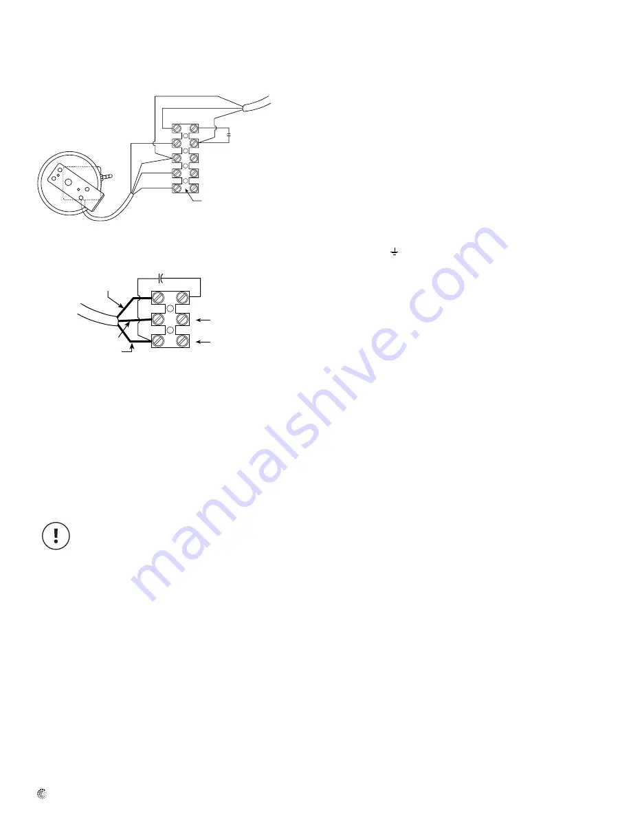
Illustration 5
DBF110 Wiring – Fan and Pressure Switch
Blue
Brown
Power
to Fan
Red
White
Black
Green
Terminal block in
fan wiring box
Neutral
115V Line (Supply) Electrical supply, 115V
Ground
Capacitor
Motor
Leads
Brown (Z2)
Blue (U2)
Black (TK)
Capacitor
Neutral side of
115V supply
Line side of
115V supply
Fan Only Wiring (Reference for Troubleshooting Step 8c)
Black
N
L
Maintenance
Prior to performing Steps 1 - 4, be certain that the electrical
supply to the fan/switch is turned off.
If fan fails to start when the dryer cycle begins, please follow the
procedure listed below:
1. Check the incoming supply for proper voltage.
2. Consult schematic shown above (also included on inside of fan wiring
terminal lid) to ensure proper connection.
3. If possible, use a meter to test for continuity across the fan motor
leads. In order to do this, the capacitor and pressure switch must be
disconnected (do not test the capacitor - it will not meter continuity).
If motor leads show continuity, rewire the fan, capacitor and
pressure switch.
4. Turn on the electrical supply and restart the dryer cycle. Check to be
certain that fan starts.
If fan still fails to start after performing Steps 1 – 4, continue following
the procedure as listed below:
5. Verify that the pressure switch diaphragm is vertical as shown in
Illustration 2 of these instructions. If the diaphragm is not vertical,
reposition the pressure switch and check for fan operation against
another dryer cycle.
6. Verify that the tubing is not crimped and that the tubing connector
nipples are not obstructed.
7. If switch diaphragm is vertical and fan still fails to start, with the
electrical supply on:
a. Remove the tubing from the nipple on the fan and blow gently
into the tubing;
b. If fan starts, consult Fantech for additional technical support.
8. If fan fails to start after blowing into the tubing:
a. Disconnect incoming power supply at the source.
b. Remove the pressure switch leads from the wiring terminal
block
c. Connect the incoming power supply directly to the fan motor
as shown in "FR110 Wiring" diagram below.
d. Turn on power to fan.
9. If fan fails to start, please consult Fantech for additional technical
support.
Recommended Maintenance
1. Since fan bearings are sealed and provided with an internal lubricating
material, no additional lubrication is necessary.
2. Fan impeller may accumulate lint. Periodic inspection, based upon
dryer usage, should be performed to ensure that the fan impeller is
not obstructed or loaded with lint. Under normal conditions, fan should
be inspected a minimum of every Six (6) Months. Note: Excessive
booster fan noise or vibration may be an indication of lint buildup on the
impeller. To inspect and clean the impeller:
a. Disconnect the incoming power supply at the source.
b. Remove the duct from the fan inlet and remove any lint buildup on the
impeller.
c. Reconnect the duct to the fan. Turn power supply on.
Troubleshooting


