background image

DBF110 DRYER EXHAUST BOOSTER SYSTEM INSTALLATION INSTRUCTIONS

DBF110 Includes:

1 DBF 110 Dryer Booster Fan

1 Fan Mounting Bracket and Hardware

1 Small Wall Sign Indicating Proper Operating Procedure

Important Notice

Read and Save these instructions for future reference.

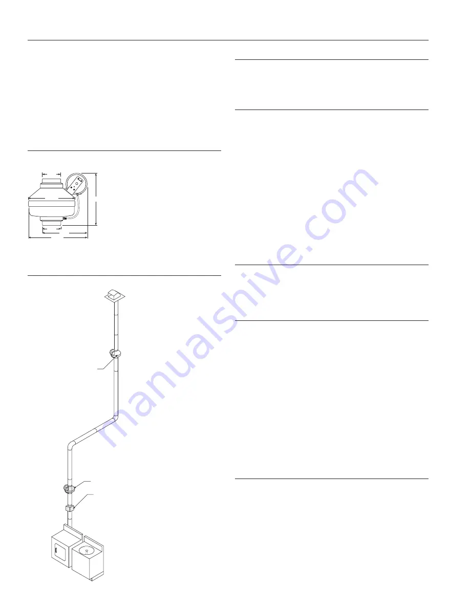
Dimensional Data

3

1

³|₄

4

12¹|₂

9¹|₂

4

9¹|₂

11¹|₄

4¹|₂

Illustration 1

(DBF110)

DBF110

Alternative Location

Secondary Lint Trap

Installation Guidelines

Please note: DBF 110 fans are not explosion proof. Do not use the fans if
a potentially explosive situation may exist.

DO NOT USE with heated air in excess 140˚F (60˚C).

Fan and Switch Mounting 

The recommended location of the booster fan is a minimum of 15 linear (not
equivalent) feet of duct from the dryer outlet. If the fan is mounted closer
than the recommended 15 feet, it may develop enough pressure to lift wet
lint into the fan impeller resulting in excessive lint loading in the fan. The best
location for the fan to be mounted is as close as possible to the termination
of the duct work. 

(Exception: If a secondary lint filter is installed between the

dryer and the booster fan, the booster fan may be mounted within the min-
imum distance otherwise recommended (See illustration to left). An NB
mounting bracket attached to a rafter or joist should be used to stabilize the
fan. Although not recommended, a vertical rigid duct may support the fan if
the duct is securely stabilized. (Consult local codes prior to supporting the
fan in the duct alone.) Duct work should be attached to the inlet and outlet
of the fan by means of FC vibration isolation clamps 

(not included) or duct

tape. The duct connection should be properly sealed to prevent leakage and
loss of fan performance. Flex duct connections between the dryer duct con-
nection and exhaust duct should be stretched as smooth as possible.

Calculating Duct Run

To calculate the length of your planned duct run, measure from the dryer
to external venting point in roof or wall. For each bend or elbow add 5-7
feet to your total duct run calculations. The DBF4XL can be used on runs
up to 108 feet.

Pressure Sensor Switch Operation 

Fantech’s DBF110 is equipped with Fantech's Patented DB10 pressure
switch. The DB10 is a positive pressure sensing switch which 
recognizes dryer operation and activates the booster fan from an 
independent electrical circuit. This eliminates connections through the
dryer circuit which may void the manufacturers’ warranty as well as man-
ual systems which require the attention of the operator or costly cur-
rent/temperature sensing systems. 

The electricity to the booster fan is connected in series through a 
normally open terminal on the switch. A pressure tap is connected to a
fitting on the side of the switch. When the dryer begins operation, posi-
tive pressure in the duct causes the switch diaphragm to expand, closing
the circuit to the booster fan. An integral delay-on-break timer in the
switch will cycle the fan on for intervals of 10 minutes. This will continue
until the dryer has stopped and the timer delay period has lapsed. Drying
cycles, the booster fan, the delay timer and the pressure switch are not
adversely affected by the starting/stopping intervals.  

Fan Installation

Step 1.  Selecting Fan Location

Fan 

must 

be mounted a minimum of 15 feet from the dryer outlet. 

If the fan is mounted closer than the recommended 15 feet, it may devel-
op enough pressure to lift wet lint into the fan impeller resulting in exces-
sive lint loading in the fan. 

(Exception: If a secondary lint filter is installed

between the dryer and the booster fan, the booster fan may be mounted
within the minimum distance otherwise recommended (See illustration to
left). The best location for the fan to be mounted, in any application, is as
close as possible to the termination of the duct work. In order to perform
recommended maintenance, fan location should allow sufficient access
for service. Refer to dimensional drawings shown above.

Summary of Contents for DBF110

Page 1: ...TER SYSTEM INSTALLATION INSTRUCTIONS DISPOSITIF DBF110 D AMPLIFICATION DU SYSTÈME DE VENTILATION DES SÉCHOIRS À LINGE INSTRUCTIONS D INSTALLATION SISTEMA DE REFUERZO DE ESCAPE DE LA SECADORA DBF110 INSTRUCCIONES DE INSTALACION ...

Page 2: ...nned duct run measure from the dryer to external venting point in roof or wall For each bend or elbow add 5 7 feet to your total duct run calculations The DBF4XL can be used on runs up to 108 feet Pressure Sensor Switch Operation Fantech s DBF110 is equipped with Fantech s Patented DB10 pressure switch The DB10 is a positive pressure sensing switch which recognizes dryer operation and activates th...

Page 3: ... SERVICE TO THE FAN IS LOCKED IN OFF POSI TION 1 This unit has rotating parts and safety precautions should be exer cised during installation operation and maintenance 2 CAUTION For General Ventilation Use Only Do Not Use To Exhaust Hazardous Or Explosive Materials And Vapors 3 WARNING TO REDUCE THE RISK OF FIRE ELECTRIC SHOCK OR INJURY TO PERSONS OBSERVE THE FOLLOWING a Use this unit only in the ...

Page 4: ... cycle Check to be certain that fan starts If fan still fails to start after performing Steps 1 4 continue follow ing the procedure as listed below 5 Verify that the pressure switch diaphragm is vertical as shown in Illustration 2 of these instructions If the diaphragm is not verti cal reposition the pressure switch and check for fan operation against another dryer cycle 6 Verify that the tubing i...

Page 5: ...sitive qui identifie le fonctionnement du séchoir et active le ventilateur d amplification à partir d un circuit électrique indépendant Cela élimine non seulement les connexions tran sitant par les circuits du séchoir ce qui peut en annuler la garantie mais aussi l installation de systèmes manuels nécessitant l attention d un opérateur ou celle de coûteux systèmes de détection électrique ou thermi...

Page 6: ...e de fabrica tion b Avant tout entretien ou nettoyage coupez le courant au tableau électrique et verrouillez ce dernier pour empêcher l activation acci dentelle du ventilateur Quand le système de coupure de courant ne peut pas être verrouillé attachez solidement sur le tableau élec trique un dispositif de signalisation bien en vue tel qu une éti quette c Les travaux d installation et de branchemen...

Page 7: ...uité n y sera mesurée Si les fils d amenée indiquent une continuité recâblez le ventilateur le capaciteur et le rupteur de pression 4 Rebranchez l alimentation électrique et redémarrez le cycle du séchoir Vérifiez que le ventilateur démarre Si le ventilateur ne démarre toujours pas après que vous êtes passés par les étapes 1 4 continuez la procédure telle qu indiqué ci dessous 5 Vérifiez que le di...

Page 8: ...nex ión de la secadora y el conducto de escape se deben estirar para que queden lo más lisas posible Operación del Interruptor Sensor de Presión El DBF110 de Fantech está equipado con un interruptor de presión DB10 paten tado por FanTech El DB10 de Fantech es un interruptor sensor de presión posi tiva que capta la operación de la secadora y activa el ventilador de refuerzo medi ante un circuito el...

Page 9: ...OR QUEDE ASEGURADA EN LA POSICION OFF DESCONECTADA 1 Debido a que esta unidad tiene piezas rotatorias se deben tomar precau ciones de seguridad durante su instalación operación y mantenimiento 2 PRECAUCION Sólo para ventilación en general No Utilizar como Extractor de Materiales Peligrosos o Explosivos ni Vapores 3 Advertencia Para reducir el riesgo de incendio conmocion electrica o lesiones perso...

Page 10: ... contactos del motor del ventilador Para esto hay que desconectar el capac itor y el interruptor de presión No compruebe el capacitor ya que el mismo no da continuidad Si los contactos del motor tienen continuidad vuelva a conectar el ventilador el capacitor y el interruptor de presión 4 Conecte la alimentación eléctrica y reactive el ciclo de la secadora Compruebe la activación del ventilador Si ...

Page 11: ...ts spécifiques reconnus par la loi et sont régies par les lois sur la protection du consommateur appro priées Il est possible que différents états offrent d autres droits Garantía por cinco 5 años DURANTE EL PERÍODO INTEGRO DE LA GARANTÍA FANTECH reparará o reemplazará toda parte que presente un defecto en el material o en la mano de obra Es posible que el producto deba ser devuelto a la fabrica F...

Page 12: ... AND VERIFICATION OF ACTUAL DEFECT BY FANTECH THE FOLLOWING WARRANTIES DO NOT APPLY Damages from shipping either concealed or visible Claim must be filed with freight company Damages resulting from improper wiring or installation Damages or failure caused by acts of Gad or resulting from improper con sumer procedures such as 1 Improper maintenance 2 Misuse abuse abnormal use or accident and 3 Inco...

Reviews: