background image

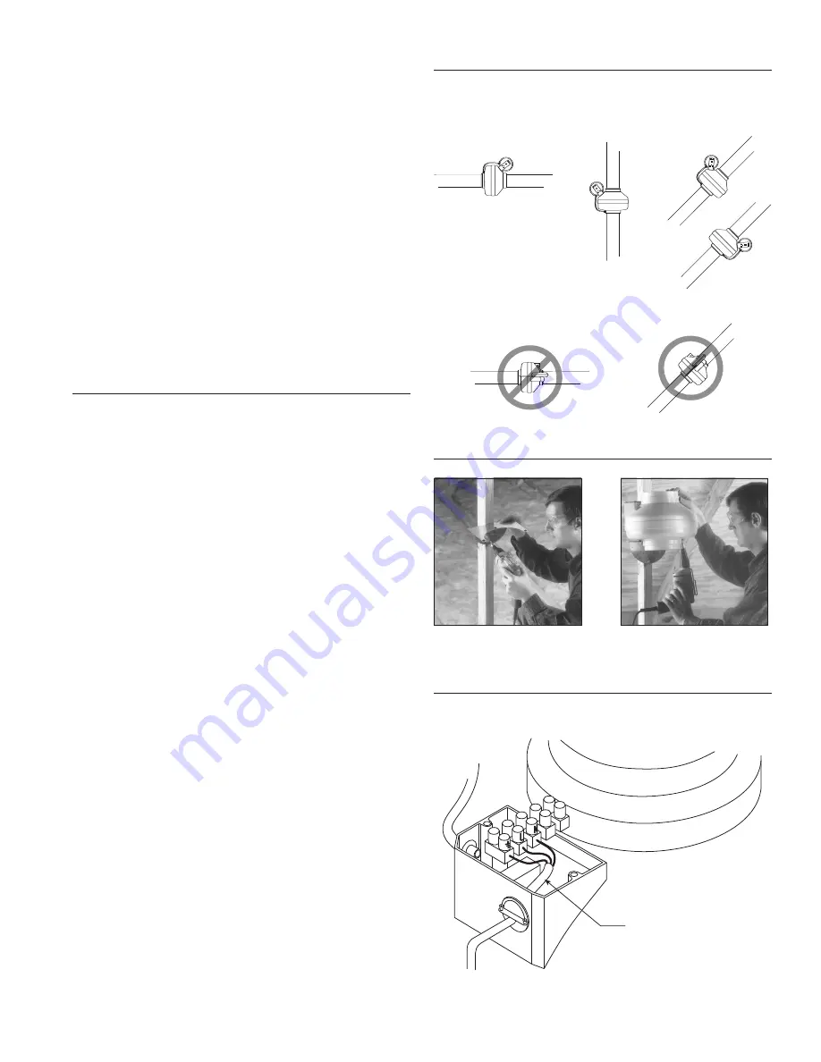
Attach Mounting Bracket to

stud using screws provided.

Attach Fan to Mounting
Bracket using screws provided.

Illustration 2

Correct Mounting of Diaphragm Switch

Horizontal

Vertical

Angled

Illustration 3

Illustration 4

Switch mounted
properly 
above and 
below 
duct.

Incorrect Mounting of Diaphragm Switch

Electrical Supply from

Breaker Panel

Switch Circuit

Step 2.  Mount Bracket

Using the wood screws provided, attach the mounting bracket to a sup-
port beam at the selected location. Bracket is provided with grommets
in order to isolate any vibration and prevent the transmission of sound
through the structure. Be careful not to overtighten. Fan mounting can
be in any angle (see ill. 2), however, vertical mounting is recommended
to reduce condensation buildup in the fan. If a horizontal installation is

necessary and condensation buildup may pose a problem, a 

¹|₄

" hole

drilled in the bottom of the housing (along with an NPT insert [by oth-
ers] and drain tubing) will allow condensation to drain.

Step 3.  Mount Fan

For proper operation, the switch diaphragm must be positioned verti-
cally. (Illustrations below show diaphragm position for horizontal, verti-
cal and ducts installed at an angle.) Wiring box should be positioned for
easy access. Attach fan to the mounting bracket with the self tapping
screws provided. Care should be taken not to strip the plastic housing.

Although screw pilot holes are not required, 

³|₃₂

" (or smaller) pilot holes

are recommended.  

NOTE:

Steps 2 & 3 may be reversed.

Electrical Connection

DO NOT CONNECT POWER SUPPLY UNTIL FAN IS COMPLETELY INSTALLED.
MAKE SURE ELECTRICAL SERVICE TO THE FAN IS LOCKED IN "OFF" POSI-
TION.

1. This unit has rotating parts and safety precautions should be exer-

cised during installation, operation and maintenance.

2.

CAUTION:

"For General Ventilation Use Only. Do Not Use To Exhaust

Hazardous Or Explosive Materials And Vapors."

3.

WARNING: TO REDUCE THE RISK OF FIRE, ELECTRIC SHOCK, OR
INJURY TO PERSONS - OBSERVE THE FOLLOWING

:

a. Use this unit only in the manner intended by the manufac-

turer. If you have questions, contact the factory.

b. Before servicing or cleaning, switch power off at service

panel and lock service panel to prevent fan from being
switched on accidentally. When the service disconnecting
means cannot be locked, securely fasten a prominent warn-
ing device, such as a tag, to the service panel.

c. Installation work and electrical wiring must be done by qual-

ified person(s) in accordance with all applicable codes and
standards, including fire-rated construction.

d. The combustion airflow needed for safe operation of fuel

burning equipment may be affected by this unit's operation.
Follow the heating equipment manufacturer's guidelines and
safety standards such as those published by the National
Fire Protection Association (NFPA), the American Society of
Heating, Refrigeration, and Air Conditioning Engineers
(ASHRAE) and the local code authorities.

e. When cutting or drilling into wall or ceiling, do not damage

electrical wires or other hidden utilities.

f. Ducted fans must always be vented to the outdoors.

g. Install fan at least five feet above the floor.

4. WARNING! Check voltage at the fan to see if it corresponds to the

motor nameplate.

GUARDS MUST BE INSTALLED WHEN FAN IS WITHIN REACH OF PERSON-
NEL OR WITHIN SEVEN (7) FEET OF WORKING LEVEL OR WHEN DEEMED
ADVISABLE FOR SAFETY.

Switch mounted
properly above
duct.

Summary of Contents for DBF110

Page 1: ...TER SYSTEM INSTALLATION INSTRUCTIONS DISPOSITIF DBF110 D AMPLIFICATION DU SYSTÈME DE VENTILATION DES SÉCHOIRS À LINGE INSTRUCTIONS D INSTALLATION SISTEMA DE REFUERZO DE ESCAPE DE LA SECADORA DBF110 INSTRUCCIONES DE INSTALACION ...

Page 2: ...nned duct run measure from the dryer to external venting point in roof or wall For each bend or elbow add 5 7 feet to your total duct run calculations The DBF4XL can be used on runs up to 108 feet Pressure Sensor Switch Operation Fantech s DBF110 is equipped with Fantech s Patented DB10 pressure switch The DB10 is a positive pressure sensing switch which recognizes dryer operation and activates th...

Page 3: ... SERVICE TO THE FAN IS LOCKED IN OFF POSI TION 1 This unit has rotating parts and safety precautions should be exer cised during installation operation and maintenance 2 CAUTION For General Ventilation Use Only Do Not Use To Exhaust Hazardous Or Explosive Materials And Vapors 3 WARNING TO REDUCE THE RISK OF FIRE ELECTRIC SHOCK OR INJURY TO PERSONS OBSERVE THE FOLLOWING a Use this unit only in the ...

Page 4: ... cycle Check to be certain that fan starts If fan still fails to start after performing Steps 1 4 continue follow ing the procedure as listed below 5 Verify that the pressure switch diaphragm is vertical as shown in Illustration 2 of these instructions If the diaphragm is not verti cal reposition the pressure switch and check for fan operation against another dryer cycle 6 Verify that the tubing i...

Page 5: ...sitive qui identifie le fonctionnement du séchoir et active le ventilateur d amplification à partir d un circuit électrique indépendant Cela élimine non seulement les connexions tran sitant par les circuits du séchoir ce qui peut en annuler la garantie mais aussi l installation de systèmes manuels nécessitant l attention d un opérateur ou celle de coûteux systèmes de détection électrique ou thermi...

Page 6: ...e de fabrica tion b Avant tout entretien ou nettoyage coupez le courant au tableau électrique et verrouillez ce dernier pour empêcher l activation acci dentelle du ventilateur Quand le système de coupure de courant ne peut pas être verrouillé attachez solidement sur le tableau élec trique un dispositif de signalisation bien en vue tel qu une éti quette c Les travaux d installation et de branchemen...

Page 7: ...uité n y sera mesurée Si les fils d amenée indiquent une continuité recâblez le ventilateur le capaciteur et le rupteur de pression 4 Rebranchez l alimentation électrique et redémarrez le cycle du séchoir Vérifiez que le ventilateur démarre Si le ventilateur ne démarre toujours pas après que vous êtes passés par les étapes 1 4 continuez la procédure telle qu indiqué ci dessous 5 Vérifiez que le di...

Page 8: ...nex ión de la secadora y el conducto de escape se deben estirar para que queden lo más lisas posible Operación del Interruptor Sensor de Presión El DBF110 de Fantech está equipado con un interruptor de presión DB10 paten tado por FanTech El DB10 de Fantech es un interruptor sensor de presión posi tiva que capta la operación de la secadora y activa el ventilador de refuerzo medi ante un circuito el...

Page 9: ...OR QUEDE ASEGURADA EN LA POSICION OFF DESCONECTADA 1 Debido a que esta unidad tiene piezas rotatorias se deben tomar precau ciones de seguridad durante su instalación operación y mantenimiento 2 PRECAUCION Sólo para ventilación en general No Utilizar como Extractor de Materiales Peligrosos o Explosivos ni Vapores 3 Advertencia Para reducir el riesgo de incendio conmocion electrica o lesiones perso...

Page 10: ... contactos del motor del ventilador Para esto hay que desconectar el capac itor y el interruptor de presión No compruebe el capacitor ya que el mismo no da continuidad Si los contactos del motor tienen continuidad vuelva a conectar el ventilador el capacitor y el interruptor de presión 4 Conecte la alimentación eléctrica y reactive el ciclo de la secadora Compruebe la activación del ventilador Si ...

Page 11: ...ts spécifiques reconnus par la loi et sont régies par les lois sur la protection du consommateur appro priées Il est possible que différents états offrent d autres droits Garantía por cinco 5 años DURANTE EL PERÍODO INTEGRO DE LA GARANTÍA FANTECH reparará o reemplazará toda parte que presente un defecto en el material o en la mano de obra Es posible que el producto deba ser devuelto a la fabrica F...

Page 12: ... AND VERIFICATION OF ACTUAL DEFECT BY FANTECH THE FOLLOWING WARRANTIES DO NOT APPLY Damages from shipping either concealed or visible Claim must be filed with freight company Damages resulting from improper wiring or installation Damages or failure caused by acts of Gad or resulting from improper con sumer procedures such as 1 Improper maintenance 2 Misuse abuse abnormal use or accident and 3 Inco...

Reviews: