

4
fantech
Flexible Duct Installation Hints
Fantech strongly recommends the use of flexible insulated duct where
ducting passes through unconditioned space or where noise is a factor.
Check local code requirements before installing. Failure to use insulated
flexible duct could result in excessive condensation buildup within the duct,
and undesirable sound levels within the room.
A minimum of 8' of insulated flexible duct is recommended between
the fan and any inlet grille. Duct should be stretched as tight and straight as
possible. Failure to do so could result in dramatic loss of system
performance. Connect flex duct to the fan with plastic zip ties or duct tape.
Connections should be airtight as possible for maximize performance.
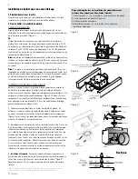
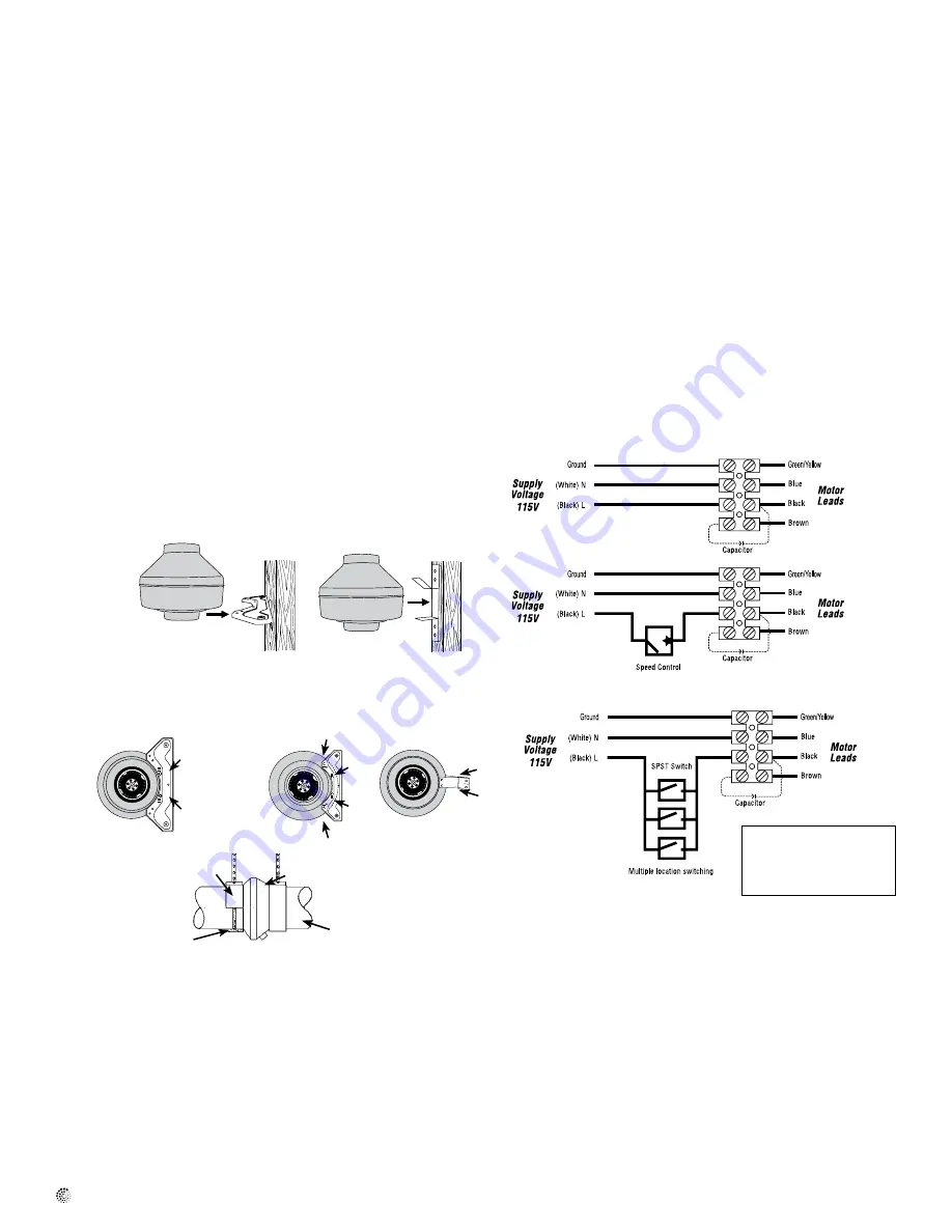
Installating Fan and Bracket
1. Before selecting mounting location for fan, consider the following:
a) Mounting the fan as far as possible from the intake point will assure
quiet operation. A minimum of 8’ of insulated flexible duct is
recommended between exhaust grille and fan.
b) Place fan where it can be easily accessed for service.
2. Attach the mounting bracket to a support beam with wood screws
provided. Fan can be mounted at any point along the duct and at any angle.
Vertical mounting is recommended to reduce condensation in the fan. For
horizontally mounting, either wrap insulation around the fan or drill a 1 1/4"
hole in the bottom of the housing. Add NPT insert and drain tube (purchased
separately) for drainage of condensation .
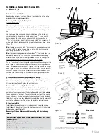
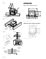
3. For PB Series fans, if bracket is used to mount fan, refer to illustration 1. If
suspending fan with hanger straps, refer to illustration 2.
4. Connect duct to inlet and outlet of fan using plastic ties or duct tape
(purchased separately). When using insulated flexible duct, the inner vinyl
core should be clamped or taped to the inlet and outlet and the vapor
barrier surrounding the insulation should be duct taped to the fan housing.
Note:
Steps 2 & 3 may be reversed.
Fantech recommends insulated flexible duct for all bathroom exhaust
applications.
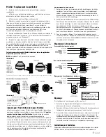
Electrical Connection
1. Remove the screws securing the terminal box cover located on the fan
motor mounting bracket. All fan motor and capacitor connections are pre-
wired to an electrical terminal strip. A 3/8" romex type cable restraint
connector will be needed to secure the wiring through the knockout on the
side of the terminal box.
2. Bring incoming electrical service through the romex connector and the
fan electrical service opening. Be sure to place the connector nut over the
wiring coming into the terminal box. There are two open ports on the
terminal strip. Using a small regular screwdriver, tighten the neutral (white)
wire of the incoming supply under the open terminal strip port labeled “N”.
Tighten the line (black) wire of the incoming supply under the open terminal
strip port labeled “L” to the ground connection on the terminal block.
3. Secure the romex connector. Secure the incoming supply with the romex
connector. Place the capacitor back into the terminal box. Replace the fan
terminal box cover. All fan motor and capacitor connections have been pre-
wired from the factory. No additional fan wiring is necessary.
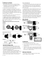
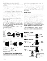
Wiring Diagrams
Troubleshooting
If fan fails to operate, please check the following:
1. Consult wiring diagrams (above) to ensure proper connection.
2. Check motor lead wiring, capacitor leads and incoming supply leads to
insure definite contact.
3. If possible, use a meter to test for continuity across the fan motor leads.
In order to do this, the capacitor must be disconnected (do not test the
capacitor - it will not meter continuity). If motor leads show continuity,
consult factory for a replacement capacitor.
Maintenance Instructions
Since fan bearings are sealed and provided with an internal lubricating
material, no additional lubrication is necessary.
Multiple Location Switching Wiring Diagram
With Motor Speed Controller
Without Motor Speed Controller
WARNING
Maximum torque that can be
applied to the terminal block
screws is 0.79 Nm (7 lb-in).
Illustration 1
Fan bracket should be installed, then fan mounted directly to bracket using sheet metal screws.
Illustration 2
Fans may be suspended
without special
mounting brackets.
Clamp Fastener
Duct Fan
Spiral duct
Vibration absorbing material
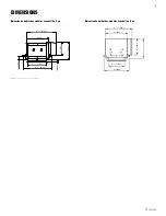
Mounting Bracket & Screw Locations for FG
• PB190
• PB270-2
• PB270F-2
• PB270H-2
• PB270FV-2
• PB270HV-2
• PB110
• PB110F
• PB110H
• PB190
• PB270-2
• PB270F-2
• PB270H-2
• PB270FV-2
• PB270HV-2
• PB370-2
• PB110
• PB110F
• PB110H
• PB370-2


