
Specification
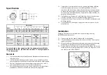
Dimensions
Model
A B C D E F G H J
Weight
kg
RIL-150SW 112 60 100
80
295
147 200 225
236 2.7
RIL-200SW
124 94 108.5 100 302 198 217 235
265
4.9
Speed
Speed r/min
Electrical
Data
Model
FLC
Amps
Input
W
RIL-150SW
HIGH ( II )
2500
0.22
50
LOW ( I )
1950
0.19
44
RIL-200SW
HIGH ( II )
2500
0.50
120
LOW ( I )
2000
0.45
100
To select high or low speed, switch the speed selector fitted to
the side of the unit’s junction box to either “II” for high speed or
“I” for low speed.
General
1.1. It is important that these Installation and Maintenance Instructions are
fully adhered to.
1.2. All electrical installations must be carried out by a suitably qualified
and competent personnel in accordance with all statutory requirements.
1.3. The fan is designed for use in an ambient temperature of up to 40°C.
It is not suitable for corrosive or explosive atmospheres.
1.4. The installer should provide easy access to the fan to facilitate future
maintenance, and ensure that the fan is adequately supported.
1.5 This product is not intended for use by persons (including children)
with reduced physical sensory or mental capabilities, or lack of
experience and knowledge, unless they have been given supervision
or instruction concerning use of the product by a person responsible
for their safety. Children should be supervised to ensure that they do
not play with the product.
1.6 Precautions must be taken to avoid back-flow of gases into the room
from the open flue of gas or other fuel burning appliances.
1.7 A minimum of one (1) metre of duct is to be fitted to the fan inlet and
discharge spigots.
1.8 To avoid a hazard, a damaged supply cord must be replaced by the
manufacturer.
Installation
Warning: The fan must be isolated from the power supply during
installation and maintenance.
2.1. Upon receipt, the fan should be inspected for any damage.
2.2. Check the details on the rating plate to ensure that the correct power
supply is available
2.3. Means for electrical disconnection must be incorporated in the wiring
installation in accordance with the relevant wiring regulations.
2.4. Remove the fan body from the spigots that are attached to the base by
releasing the two retaining clamps (RIL-150SW, see diagram), or the
two clamp screws (RIL-200SW).


