12
Airflow adjustment & balancing
Commissioning the system after installation is recommended which include confirming the proper operation of the system and how it interacts with
other components within the home.
Airflow station grid method
B
Measure
here
Measure
here
12”
(300 mm)
12”
(300 mm)
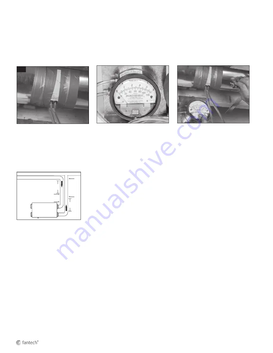
1
For this flow measuring station, cut the
duct and place the flow measuring station
between each section of duct. Make sure
that the flow measuring station's air
direction arrow points in the direction of
the airflow. Secure the flow measuring
station with duct tape.
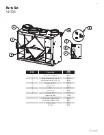
2
Before taking the reading, make sure that
the megnehelic gauge is level and at 0.
Refer to the flow measuring station's
chart to determine your unit's airflow
velocity.
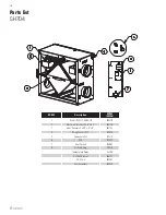
3
Adjust the "Supply Air Out" damper until
you reach the desired velocity. Follow the
previous steps to adjust the "Exhaust Air
Out" damper, if needed.
•
To avoid airflow turbulence and
incorrect readings, the airflow
velocity should be measured on
steel ducting a minimum of 12"
(300 mm) from the unit or elbow
and before any transition.


