background image

5

fantech

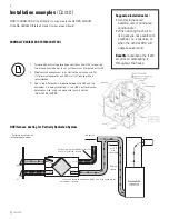
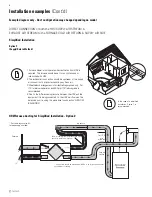
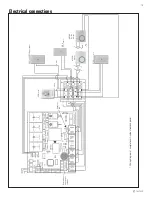
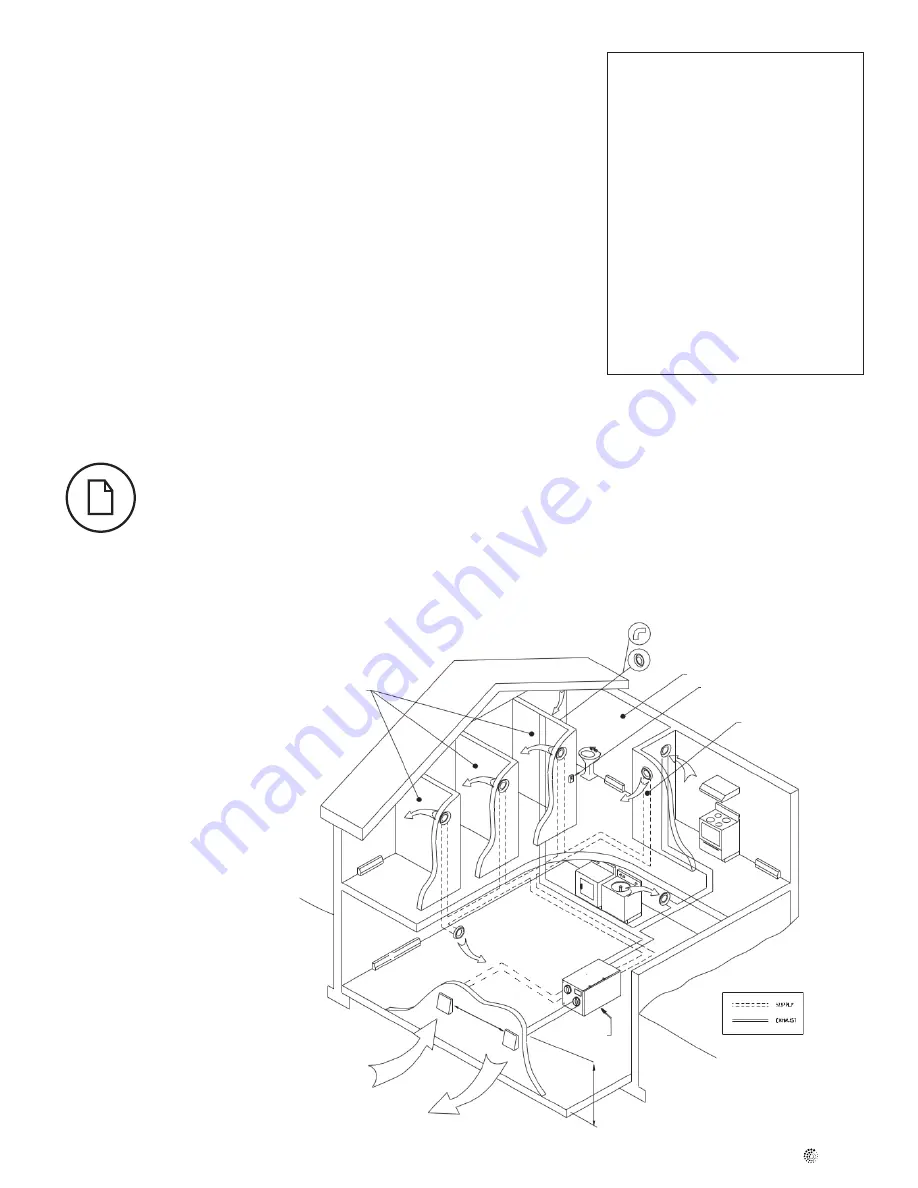
Installation examples

Example only – duct configuration may differ depending on the model.

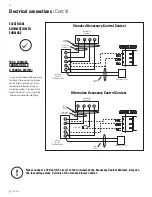
FULLy DEDICATED SySTEM  

BEST FOR NEw CONSTRUCTION

Stale air is drawn from key areas of home (bathroom, kitchen, laundry)
Fresh air supplied to main living areas

Bathroom

Bedrooms

Fresh Air

Exhaust Air

Central Control - optional

Fresh air to living room

Exhaust CG 4 (4” Adjustable Grill)

FEL 4 (4” Miter Elbow)

460 mm

3m

HRV

1. Furnace blower must operate when ventilation from HRV is required. The 

furnace should be set to run continuously or interlocked with HRV.

2. Weatherhood arrangement is for illustrative purposes only. 3m (10')      

minimum separation and 460 mm (18") above grade is recommended.

3. Due to the differences in pressure between the HRV and the equipment it is 

being connected to, the HRV's airflow must be balanced on site, using the 
procedure found in section “AIRFLOW BALANCING”.

Suggested installation for:

• 

Hydronic baseboard

• 

Infloor heating

• 

Electric baseboard

• 

Mini split heat pump

Benefits: 

Provides the best 

fresh air distribution in the 
house; lowest operation cost 
since the furnace/air handler 
unit is not needed.

Summary of Contents for SHR series

Page 1: ...ith the current edition of the National Building Code and or ASHRAE s Good Engineering Practices Fantech reserves the right to modify at any time and without notice any or all of its products features...

Page 2: ...vented combustion equipment i e Gas Furnaces Oil Furnaces Wood Stoves etc Products are designed and manufactured to provide reliable performance but they are not guaranteed to be 100 free of defects E...

Page 3: ...herhood Location 9 Installing the ducting to the weatherhood 9 Steps for hood installation 9 INSTALLING DUCTS TO FROM INSIDE Installing ducting to HRV 10 Supply Exhaust Air Grilles Location 10 Ducting...

Page 4: ...loor area Bedrooms 0 1 2 3 4 5 6 7 7 Ft2 m2 CFM L s CFM L s CFM L s CFM L s CFM L s 1500 139 30 14 45 21 60 28 75 35 90 42 1501 3000 139 1 279 45 21 60 28 75 35 90 42 105 50 3001 4500 279 1 418 60 28...

Page 5: ...tion from HRV is required The furnace should be set to run continuously or interlocked with HRV 2 Weatherhood arrangement is for illustrative purposes only 3m 10 minimum separation and 460 mm 18 above...

Page 6: ...t it is being connected to the HRV s airflow must be balanced on site using the procedure found in section AIRFLOW BALANCING HRV Furnace ducting for Partially Dedicated System Stale air coming from di...

Page 7: ...separation and 460 mm 18 above grade is recommended 5 Due to the differences in pressure between the HRV and the equip ment it is being connected to the HRV s airflow should be balanced on site using...

Page 8: ...d 460 mm 18 above grade is recommended 4 Due to the differences in pressure between the HRV and the equipment it is being connected to the HRV s airflow must be balanced on site using the procedure fo...

Page 9: ...e outer liner which acts as a vapor barrier must be completely sealed to the outer wall and the HRV using tape and or caulking A good bead of high quality caulking preferably acoustical sealant will s...

Page 10: ...d from high wall or ceiling locations Grilles that diffuse the air comfortably are recommended In homes with a forced air furnace you may want to connect the HRV to the furnace ductwork see informatio...

Page 11: ...The HRV and all condensate lines must be installed in a space where the temperature is maintained above the freezing point A P trap should be made in the drain line This will prevent odors from being...

Page 12: ...YOUR HOME WHICH CAN LEAD TO AIR LEAKS OR BACKDRAFTING OF ANY COMBUSTION APPLIANCES The balancing procedure consists of measuring the supply air flow and the return air flow to ensure that they are eq...

Page 13: ...also be made prior to any transition in the duct work so entire airflow is measured Measuring the airflow using station grid method Adjusting airflows A damper is integrated into the Fresh Air to Buil...

Page 14: ...dity exceeds the desired level the ventilation system operates at HIGH speed Once the desired humidity level is achieved your system resumes its normal mode of operation Allows occupants to control th...

Page 15: ...ection switch Diagnostic LED U RTS 2 up to 5 timers MDEH 1 2 wires MDEH 2 On Off 4 wires and or 1 only CUR SW DEHUM N C N O TIMER EDF COM FURNACE INTERLOCK IN COM ECO Touch EDF1 and EDF1R not shown RT...

Page 16: ...t d electrical connection to furnace For a Furnace Connection to a Cooling System On some older thermostats energizing the R and G terminals at the furnace has the effect of energizing Y at the thermo...

Page 17: ...uate power supply at site Have electrician check supply voltage Ductwork is restricting airflow Check duct installation Improper speed control setting Increase the speed of the HRV i e change unit con...

Page 18: ...uential damages incurred in the use of the ventilation system Fantech is not responsible for providing an authorized service centre near the purchaser or in the general area Fantech reserves the right...

Page 19: ...19 fantech NOTES...

Page 20: ...20 fantech NOTES...

Page 21: ...tional du b timent du Canada ou aux m thodes d ing nierie appropri es de l ASHRAE Fantech se r serve le droit de modifier partiellement ou enti rement en tout moment et sans pr avis les caract ristiqu...

Page 22: ...ils de chauffage vacuation fournaise gaz fournaise mazout po le bois etc Les produits sont con us et fabriqu s pour fournir une performance fiable mais ils ne sont pas garantis 100 sans d faut M me le...

Page 23: ...e de conduit avec hottes 29 tape de l installation de la hotte 29 INSTALLATION DES CONDUITS INT RIEUR Installation des conduits sur le VRC 30 Emplacement des grilles d approvisionnement et d vacuation...

Page 24: ...air recommand Superficie Chambre coucher 0 1 2 3 4 5 6 7 7 pi2 m2 Pi3 min L s Pi3 min L s Pi3 min L s Pi3 min L s Pi3 min L s 1500 139 30 14 45 21 60 28 75 35 90 42 1501 3000 139 1 279 45 21 60 28 75...

Page 25: ...s endroits cl s de la maison salle de bains cuisine buanderie 2 L air frais est distribu parmi les pi ces habitables chambres coucher salon 3 Le d bit d air du VRC doit tre confirm sur place au moyen...

Page 26: ...enant de diff rentes pi ces de la maison p ex salle de bains au besoin cuisine au besoin L appareil est g n ralement quilibr haute vitesse et pendant que le ventilateur de la fournaise est en marche R...

Page 27: ...En raison de l cart de pression entre le VRC et l quipement auquel il est raccord le d bit d air du VRC doit tre quilibr sur place au moyen de la proc dure d taill e dans la section quilibrage du d bi...

Page 28: ...e du pr sent manuel d installation 4 Pour fins d acceptation v rifiez aupr s des autorit s locales au sujet des codes du b timent propres votre r gion Exemple d installation suite Dans le cas d une in...

Page 29: ...l tement scell sur le mur ext rieur et le VRC l aide de ruban ou de produit de calfeutrage D posez un cordon de produit de calfeutrage de premi re qualit du mastic d isolation acoustique de pr f rence...

Page 30: ...oucher L air devrait provenir de la partie sup rieure d un mur ou du plafond Il est recommand d utiliser des grilles qui distribuent l air confortablement Dans les maisons pourvues d une fournaise air...

Page 31: ...de la condensation L eau de condensation doit s couler vers le drain avoisinant ou tre aspir e par une pompe condens t Le VRC et toutes les canalisations de condens t doivent tre install s dans un en...

Page 32: ...ER UNE PRESSION N GATIVE OU POSITIVE DANS VOTRE MAISON FAISANT ENTRER L AIR FROID OU CAUSANT UN REFOULEMENT DE L AIS DANS VOS APPAREILS DE CHAUFFAGE VACUATION IL ES POSSIBLE QUE LE D GIVRAGE DE L APP...

Page 33: ...es conduits afin de mesurer le d bit entier de l air Mesure du flot d air en utilisant la m thode du poste de mesure des d bits Ajustement des d bits d air Un registre est int gr dans le collet d air...

Page 34: ...e de ventilation est activ haute vitesse Une fois le niveau d humidit voulu est atteint le syst me reprend son mode d op ration normal Permet l occupant de contr ler le niveau d humidit l int rieur de...

Page 35: ...ch EDF1 and EDF1R not shown RTS3 observe polarity Wiring diagram of complete unit inside of access panel 2 wires 2 wires Respectez la polarit sur tous les accessoires de contr le le cas ch ant EDF1 ou...

Page 36: ...ue l excitation de la borne Y du thermostat et cons quemment la mise sous tension du syst me de refroidissement Si votre syst me est muni d un tel type de thermostat vous devez respecter le c blage de...

Page 37: ...fficacit du VRC V rifiez le r seau de conduits Mauvais r glage de la commande de vitesse Augmentez la vitesse du VRC i e changez la vitesse de l appareil de vitesse R DUITE vitesse NORMALE avec le con...

Page 38: ...nu de respecter tous les codes en vigueur dans sa r gion Les pi ces y compris les pi ces de rechange pos es ult rieurement sont garanties pendant 5 ans partie de la date d achat de l appareil Les mote...

Page 39: ...39 fantech Notes...

Page 40: ...to make technical changes For updated documentation please refer to www fantech net Fantech Fantech se r serve le droit de faire des changements tech niques Pour de la documentation jour s il vous pl...

Reviews: