126
126
CHAPTER 18
ENGINE
WORKSHOP MANUAL
TL 250
18.7 CRANKCASE, CRANKSHAFT, GEARBOX AND BALANCER
SHAFT
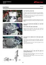
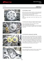
18.7.1 Removing the crankcase
Set the left crankcase down with its internal side facing up.
Remove the eight M6×65 bolts and five M6×45 bolts, separate
the left crankcase from the right and remove the 2 dowel pins.
18.7.2 Remove the crankshaft, balancer shaft, mainshaft
and countershaft
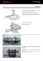
Remove the crankshaft assembly, balancer shaft, gearshift
fork shaft, gearshift fork, shift drum, mainshaft assembly and
countershaft assembly.
Make sure you do not miss any of the mainshaft assembly and
countershaft assembly components.
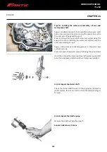
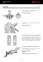
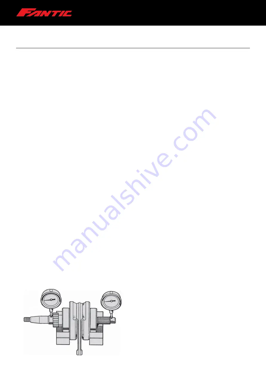
18.7.3 Inspect the crankshaft
Set the crankshaft on a pair of V-blocks.
Using a dial gauge, measure the crankshaft's radial runout.
Actual radial runout must be 50% of the TIR value.
Service limit value: 0.1 mm
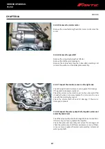
18.6.13 Install the generator stator
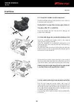
Secure the magnet stator assembly on the crankshaft on the left side by tightening the two M5×10 screws and M5×30 screws.
Torque setting: Generator stator screws: 7 to 9 Nm.
18.6.14 Install the crankcase cover on the left side
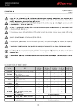
Remove the old gasket and replace it.
Fit the crankcase cover on the left side and secure with the M6×35 bolts.
Torque setting: Crankcase cover bolts on left side: 11 to 13 Nm.
Summary of Contents for TL 250
Page 1: ...1 WORKSHOP MANUAL E N...
Page 3: ...WORKSHOP MANUAL TL 250...
Page 11: ...11 WORKSHOP MANUAL TL 250...
Page 30: ...30 WORKSHOP MANUAL TL 250 CHAPTER 6 DASHBOARD 39 GENERAL CONTENT AND CONSULTATION ENGLISH...
Page 49: ...49 49 WORKSHOP MANUAL TL 250...
Page 51: ...51 CHAPTER 15 ELECTRICAL DEVICES 51 WORKSHOP MANUAL TL 250...
Page 136: ...136 136 WORKSHOP MANUAL TL 250...

