13
WORKSHOP MANUAL
TL 250
CHAPTER 2
MAINTENANCE RULES
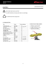
Part
Screw
Torque setting Nm
Triple clamp screw
M8 (08.8)
18
M8 (10.9)
25 +
243
Wheel axle
M14
50
Rear wheel axle nut
M17
80
M8 (08.8)
25
M8 (08.8)
25
M10 (08.8)
45
Clutch/Brake pump collars
Engine mounting screws diameter 10
Engine mounting screws diameter 8
M6 (10.9)
10
M10
45
M8
25
Swingarm pivot bolt
M14
60
Linkage
M
12
50
Rear shock
Sprocket screws
M10 upper
40
M
10 lower
40 +
243
M8 (10,9)
25
Front brake disc screws
M8
25 +
243
Rear brake disc screws
M6
10 +
243
Kickstand screw
M8 (10.9)
25
Rear brake lever screw
M10 (8.8)
40
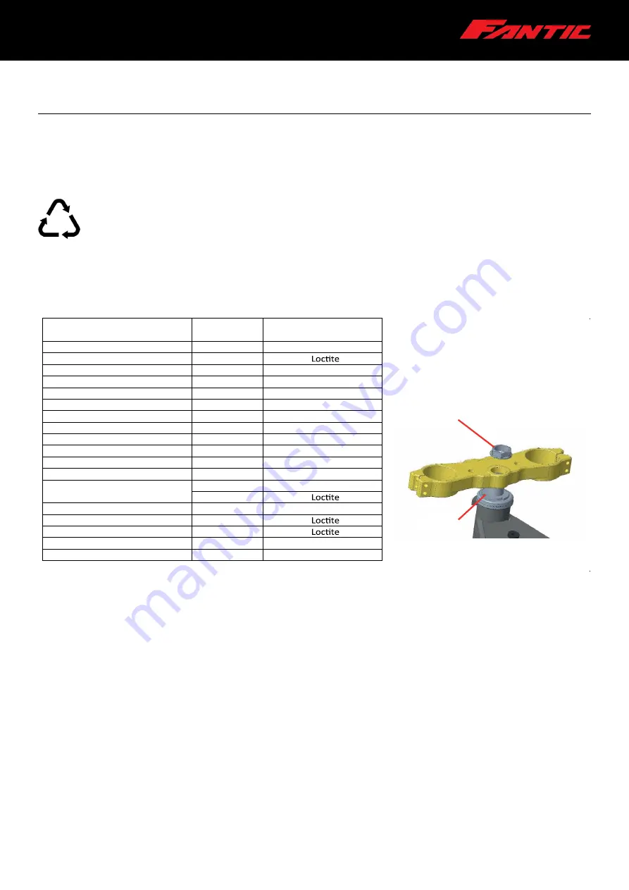
STEERING STEM FASTENING SEQUENCE:
1. Tighten the ring nut to 25Nm;
2. Loosen the ring nut ½ a turn;
3. Retighten the ring nut to 8 Nm;
4. Fit the upper triple clamp;
5.
Tighten the top nut to 80 Nm.
NUT
RING NUT
Front brake caliper screws
Fork axle clamp screws
Handlebar bolts
Handlebar bolts
!
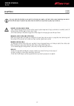
Keep all parts away from sources of heat.
Do not lift the vehicle by its licence plate bracket, to avoid damage.
Use suitable tools and cleaning products.
2.3 TORQUE SETTINGS
Summary of Contents for TL 250
Page 1: ...1 WORKSHOP MANUAL E N...
Page 3: ...WORKSHOP MANUAL TL 250...
Page 11: ...11 WORKSHOP MANUAL TL 250...
Page 30: ...30 WORKSHOP MANUAL TL 250 CHAPTER 6 DASHBOARD 39 GENERAL CONTENT AND CONSULTATION ENGLISH...
Page 49: ...49 49 WORKSHOP MANUAL TL 250...
Page 51: ...51 CHAPTER 15 ELECTRICAL DEVICES 51 WORKSHOP MANUAL TL 250...
Page 136: ...136 136 WORKSHOP MANUAL TL 250...


