56
CHAPTER 15
ELECTRICAL DEVICES
56
WORKSHOP MANUAL
TL 250
13
26
39
1
14
27
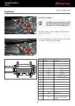
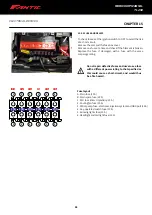
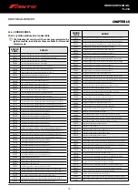
15.5.1 ECU
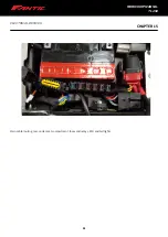
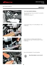
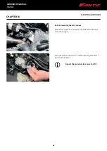
The ECU (electronic injection) is located under the seat -
refer to the procedures below:
- Removing the seat
- Ignition module
To check the ECU's wires, you are advised to unplug the
connector from the module.
10 Electrical system and devices
52
WORKSHOP MANUAL
CHAPTER 10
ELECTRICAL SYSTEM AND DEVICES
250 Rev00 / 2019
13
26
39
1
14
27
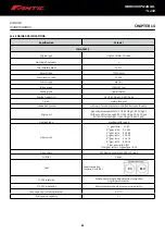
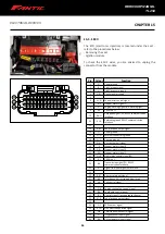
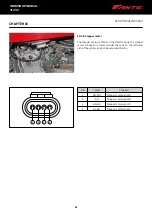
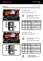
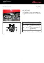
10.3.14 Engine control unit
The engine control unit (electronic injection) is located under the
saddle: refer to the procedure “12.1 Seat removal” on page 122“
and to the procedure “10.6 Ignition module” on page 83“.
To carry out checks on the control unit wires, it is advisable to
disconnect the connector from the module.
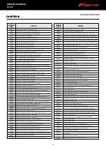
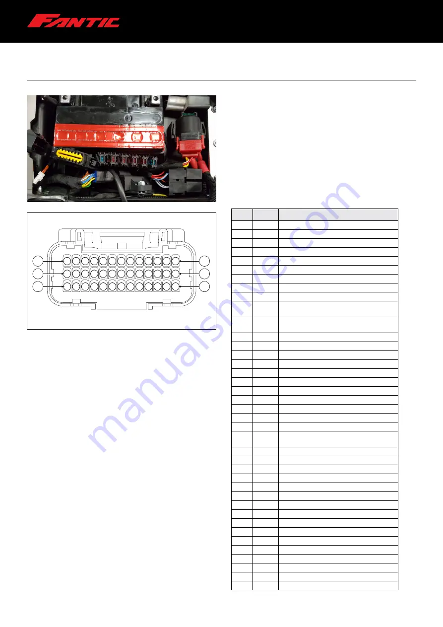
Pin
Colour
Function
1
N
Power ground
2
Bi
Pick Up input signal
3
N
Pick Up sensor ground
4
V-Bi
Sensor power supply
5
-
-
6
Ar-N
Fuel injector control signal
7
B-V
Stepper motor signal D
8
Vi
Engine warning signal (MIL warning light)
9
Az
CAN Line H
10
Ro-N
Reception signal (RX) RS232 communication
interface
11
Vi-B
Reference ground RS232 communication
interface
12
-
-
13
B-Bi
Vehicle speed output signal
14
N
Power ground
15
Vi-N
External connectors ground
16
Vi-N
Sensors ground
17
M-Vi
Key consent exit signal
18
V
Stepper motor signal B
19
V-Bi
Stepper motor signal A
20
V-N
Stepper motor signal C
21
Gr-B
Lights relay control signal (85)
22
Bi
CAN Line L
23
B-G
Transmission signal (TX) RS232
communication interface
24
Bi
Signal from neutral gearshift switch
25
-
-
26
B-M
Air pressure input signal
27
R-V
Injection unit direct supply from fuse 6
28
G-N
Coil control signal
29
-
-
30
G-R
Engine cooling fan control signal
31
B-N
Fuel pump control signal
32
Bi
Control signal (-) oxygen sensor heater
33
M-R
Vehicle speed output signal
34
-
-
35
G-V
ECR consent signal
36
Bi-N
Side kickstand position signal
37
G-B
Throttle position control signal
38
N
Oxygen sensor input signal
39
B-N
Air temperature input signal
Summary of Contents for TL 250
Page 1: ...1 WORKSHOP MANUAL E N...
Page 3: ...WORKSHOP MANUAL TL 250...
Page 11: ...11 WORKSHOP MANUAL TL 250...
Page 30: ...30 WORKSHOP MANUAL TL 250 CHAPTER 6 DASHBOARD 39 GENERAL CONTENT AND CONSULTATION ENGLISH...
Page 49: ...49 49 WORKSHOP MANUAL TL 250...
Page 51: ...51 CHAPTER 15 ELECTRICAL DEVICES 51 WORKSHOP MANUAL TL 250...
Page 136: ...136 136 WORKSHOP MANUAL TL 250...

