background image

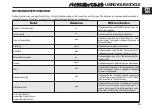
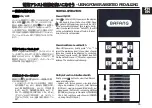
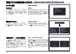
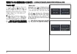
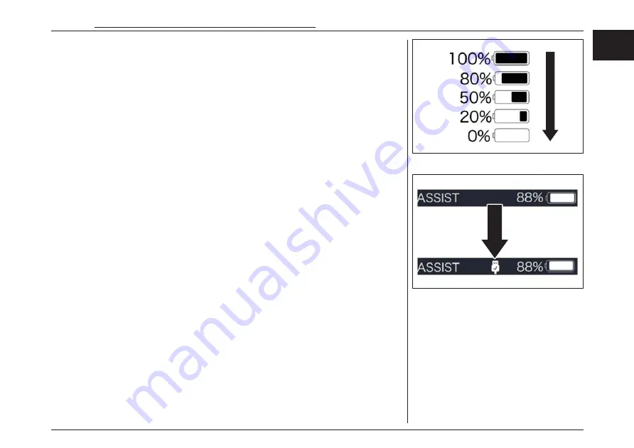
Battery Capacity Indication


The percentage of current battery capacity and  

total capacity is displayed from 100% to 0% ac-  

cording to the actual capacity (as shown in the  

figure below).


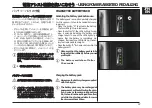
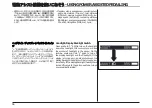
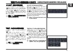
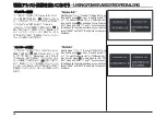
USB Charge Function


When the HMI is off, insert the USB device to the  

USB charging port on the HMI, and then turn on  

HMI to charge. When the HMI is on, can direct  

charge for USB device. the maximum charging  

voltage is 5V and the maximum charging current  

is 500 mA.


バッテリー容量の表示


現在の電池容量と総容量の割合は、実際の電
池容量に応じて

100

%から

0

%まで表示されま

す(右図参照)。


USB

充電機能


電源がオフの状態で、

USB

デバイスを

HMI

USB

充電ポートに挿入し、次に電源をオンにす

ると充電が可能です。最大充満電圧は

5V

、最大

充電アンペアは

500mA 

です。


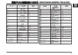
電動アシスト機構を使いこなそう

 - USING POWER ASSISTED PEDALLING 

57


EN


JPN


Summary of Contents for Issimo

Page 1: ......

Page 2: ...MPONENTS ISSIMOURBAN 18 CONTROLS ON THE HANDLEBAR ISSIMOFUN ANDURBAN 20 TECHNICALDATA 21 DESCRIPTIONOFTHE BICYCLE 22 Brakes 22 Gearshift 22 Frameand fork 23 Wheelunits 23 Electrical devices 24 Battery...

Page 3: ...JUSTMENT 38 USINGYOURBICYCLE 39 GENERALSUGGESTIONS 39 GEARSHIFTUSE 40 USEOFBRAKES 41 USINGYOURBICYCLE 42 WHATTODOFOLLOWINGAFALL 43 HOWTOTRANSPORTYOURBICYCLE 43 NOTESONBATTERYDURATION 45 USINGPOWERASSI...

Page 4: ...ALSensitivity Setlight sensitivity 60 TRIPReset Setresetfunction for single trip 61 Vibration Setthe button vibration 61 Service Turnon off the Serviceindication 62 AssistMode Setthe assist level 62...

Page 5: ...CEOPERATIONS 76 Removingand remounting the wheelsunits 76 Front wheel disassembly 76 Front wheel assembly 77 Rearwheel disassembly 78 Rearwheel assembly 81 FLATTYRE 83 OTHEROPERATIONS 86 WINTERSTORAGE...

Page 6: ...ed pedalling offers a more comfortable ride without detracting any thing fromthe healthy pleasure of cycling This bicycle has beenmanufac turedusingthehighestqualitymaterialsin conformitywithall theap...

Page 7: ...ving a maximumcontinuous rated power of 0 6kW If the proportional assistance speed is between 0 and 10 km h the assistance ratio is no more than 1 2 When the speed of acceleration is between 10 km h a...

Page 8: ...ent N B This symbol indicates important information designed to helpyougetthebestoutofyourbicycle RESPECTTHERECOMMENDEDTIGHTENINGTORQUE Thissym bolindicates that it is important toapplythe correcttigh...

Page 9: ...per sons it must be accompanied by this user and maintenance handbook The documentation this booklet safety recommendation booklet CE Declaration of Conformity Warranty etc is an integral part of the...

Page 10: ...Correctuse The bicycle subject of this manual is suitable for use both off roadand orontheroad accordingtothatstatedin Roadcondi tionstable Usingthebicycleforanyotherpurposethanthatit hasbeende signed...

Page 11: ...ISSIMOFUN ISSIMOURBAN X X BMX X X X X X X X SAFETYI NF O RMATI ON 10...

Page 12: ...on publicpath Off road Pavedtouristictrack Undemandingterrainwithslightormediumgradientsreason ableflat Un pavedtourist track Terrainwithexposedroots protrusions etc X X Sportsterrain Terraindesignedf...

Page 13: ...n com pliancewiththelocallyapplicableregulations Theitemsofthepackaging plasticbags polystyrene straps etc must not be leftwithinthereachofchildren IDENTIF IC A T IO NPLATE Each bicycle is equipped wi...

Page 14: ...1 1 5 0 m m 1 7 3 5 m m M I N 850 m m M A X 980 m m M A X 980 m m 790m m FUN EXTERNALD IM ENS IONS FUN EN DESCRIPTIONANDTECHNICALD A T A 13 JPN...

Page 15: ...1 1 5 0m m 1 7 3 5m m M I N 850 m m M A X 980 m m M A X 980 m m 790m m URBAN EXTERNALD IM ENS IONS URBAN DESCRIPTIONANDTECHNICALD A T A 14...

Page 16: ...onents arepresent 1 Rightpedal 2 Leftpedal 3 Batterycharger 4 Batterychargerpowercable 5 Useand maintenance booklet 6 Safetywarnings booklet 7 Wheelsretroreflectors 8 Twocopiesofkeysforbatteryrelease...

Page 17: ...tterypacksupport 12 Handlebartube 13 Reartire 14 Fronttire 15 Rim 16 Tirevalve 1 Rightknob 2 Handlebar 17 Front wheel hub 3 RechargeableLi Ionbatterypack 18 Rearwheel hub 4 Batteryled 5 Headlight 6 Ta...

Page 18: ...UN 24 Leftpedal 25 Pedalcrank 26 Engine 27 Leftknob 28 Handlebarmount 29 Frontfork 30 Front brakedisc 31 Front brakecalliper 32 Rearbrakedisc 33 Rearbrakecalliper 34 Kickstand 35 Batterylock I S S I M...

Page 19: ...erypacksupport 12 Handlebartube 13 Reartire 14 Fronttire 15 Rim 16 Tirevalve 1 Rightknob 2 Handlebar 17 Front wheel hub 3 RechargeableLi Ionbatterypack 18 Rearwheel hub 4 Batteryled 5 Headlight 6 Tail...

Page 20: ...AN 24 Leftpedal 25 Pedalcrank 26 Engine 27 Leftknob 28 Handlebarmount 29 Frontfork 30 Front brakedisc 31 Front brakecalliper 32 Rearbrakedisc 33 Rearbrakecalliper 34 Kickstand 35 Batterylock I S S I M...

Page 21: ...CONTROLSONTHEHANDLEBAR I S S I M OFUNA NDURBAN 1 Frontbrakelever 2 Rearbrakelever 3 Bell 4 Controltool display 5 USBsocket 6 On Offbutton 7 Usemodeselectionbuttons 8 Gearshiftcontrol 1 2 3 4 5 USB 6 7...

Page 22: ...00 Battery Fantic ISSIMO630Wh Display Multifunction LCD Frame Aluminium Gearchangeunit Shimano Nexus5 Cranks 150mm Pinion 24th Crownwheel 40th Chain KMC1vZ1eHXNarrow 3 32 Brakesystem ShimanoMT200 Fron...

Page 23: ...euvres com ingtoacompletestandstillfromamedi umspeed approx 25km h Once the braking system has been run in the braking force will be noticeably greater Operating the brake levers too sharply maycauset...

Page 24: ...Frameandfork Thebicyclehasaframewithadampedfrontfork Wheelunits The wheelunits arecalled frontwheel and rearwheel Theunits arecomposedof Hub Gearshift intherearhub Brakedisc Spokes Rim Tire Innertube...

Page 25: ...heir use are described in chapter PEDAL ASSISTUSE Batterypack The battery pack mustbe fixed to the frame For safety reasons the battery pack can be locked to the support using one of the keys supplied...

Page 26: ...justthe position and height of the seat seechapter SEATADJUST MENT Askyourdealerforinstructionsonthetechnicaldevicesofthebicycle Fullychargethebatterypack seechapter PEDAL ASSISTUSE EACHTIMEYOUUSEYOUR...

Page 27: ...re pressure is too low it may displace the position of the tyre and inner tube on the wheel rim so that the valve assumes an oblique position In this case the base of the valvemaybe torn away from the...

Page 28: ...igher the tire pressure must be The reference values are shown in thetablebelow Considerthatthevalues showninthetablearepurelyindicative Ifin doubt contact yourdealeror atire dealer Alwaysrespectthemi...

Page 29: ...wheelunits havenot been dam agedbyforeignbodies Ifrimreflectorshavebeenfitted checkthatthey arefirmlyfixed if theyareloose removethem Seatandseatpostcheck If the seat post is not inserted deep enough...

Page 30: ...ends and using your hands try to turn the handlebars in both di rections Always forcing with your hands try to rotate the handlebarinsidethemount Always on the handlebars check that the gear shift lev...

Page 31: ...the brake calliper alternately in all directions The brakecallipermustnotmove Dirty brake discs must be cleaned im mediately The presence of oil and or greaseonthebrakediscscanreducethe braking actio...

Page 32: ...aged The chain must not have any damage at any point caused by for example curved chain links pins to be riveted that come out etc or fixed locked chain links Checkthe connection of the sprocketto the...

Page 33: ...ndinsertthekeysup plied Openthelock andlift the coverof the storage compartment Tocloseit pressit downuntil youhearaclick Checkthatall thecomponentsofthe rackareproperlysecuredbeforeriding Check that...

Page 34: ...n the tire and the mudguard Remove the foreign body beforecontinuingthetravel Otherwise fallsorseriousinjuriesmayoccur Apply thread lock on the screws to pre ventlooseningcausedbyvibrationsand shocks...

Page 35: ...ews If no specific information has been provided by the manufacturer refertothefollowing tighteningtorquevalues Threadedjoint Thread Tightening torque N m Pedals 9 16 30 Handlebarjoint expansionbolt M...

Page 36: ...rs R right and L left Screw the right pedal onto the right pedal crankturning itclockwise Usea1 5 m mspannertotightenthepedal seethe TIGHTENINGTORQUE tablein CHECKANDINSPECTIONS chapter Screwthe left...

Page 37: ...lartotheframe Tighten the two screws A and the screw B to the correct tightening torque seethe TIGHTENINGTORQUE tablein CHECK ANDINSPECTIONS chapter Toadjustthehandlebarheight Loosenthescrews C witha4...

Page 38: ...E tablein CHECKANDINSPEC TIONS chapter Seatpositionandinclinationadjustment Loosentheseatlockingnuts B Important the nuts B must be com pletely loosened almost to the end of the thread in this way the...

Page 39: ...tothe correct tighteningtorque seethe TIGHTENING TORQUE tablein CHECKANDINSPEC TIONS chapter G E A R S H I F TCONTROLA D JUSTMENT Ifyouwantto adjusttheposition ofthegearshift control Loosenthelockings...

Page 40: ...traditional way or with power assistedpedalling Werecommendthatyoufamiliarize yourselfwithyourbicyclebeforeusing power assistedpedalling Tosetoneofthemodes seechapter PEDAL ASSISTUSE Carefullyreadtha...

Page 41: ...Going up in numbering weshift to abigger gear Goingdownin numbering weshifttoasmall ergear Shifting to a smaller gear results in less gear ing up Pedalresistancedecreasesandthespeed obtained is lower...

Page 42: ...on Perform these braking exercises on flat road surfaces withlowtraffic Measurethebrakesand apply the two levers simultaneously Be careful when applying the front brake lever the presence of sand grav...

Page 43: ...irmly with your righthand Operateboththebrakelevers To move forward place your left foot on the lefthandpedalandyourrightfootontheright handpedal This action may be performed either while sitting on t...

Page 44: ...nents if damaged may result in hazardous riding conditions falls accidentsanddamagetoproperty Carefullyreadthatstatedinthesafetyrecommendationbooklet H O WTOTRANSPORTYOURBICYCLE To transport the bicyc...

Page 45: ...3 4 40 4 5 1 2 0 15 15km h Cruise Sport 3 USINGYOURBICYCLE 44...

Page 46: ...ientincreases Gearratio Decreaseswhenusing harder ratios e g 4or5 increaseswhenusing easier ratios e g 1or2 Externaltemperature Decreasesbyapprox 15 if thetemperaturefal ls below0 C Speed Decreasesexp...

Page 47: ...ith water or other liquids Ifthis hap pens donotuseit andlet it bechecked bytheretailer INTRODUCTIONTOUSE This paragraph summarizes the most important information necessary for a correct use of the po...

Page 48: ...ed If at least one LED lights up the bat teryisatleastpartiallycharged Pressthebutton A for3secondstoswitchthe batterypackoff Make sure that the battery pack is fully charged allfourLEDslit beforeyouu...

Page 49: ...dicates that the battery pack is fully charged Each LED corresponds to approx 25 of the fullcharge Disconnect the battery charger from its pow er supply and the connector from the battery pack Once th...

Page 50: ...ngontheframe Placetherubberrod A ontheforksupport B Insert and turn the key in the lock and insert the battery pack in its housing Once posi tionedreleasethekeyandremoveit W h e ninsertingthebattery t...

Page 51: ...is equipped with an assistedpedal controlinstrument Cablelabel identification isasfollowing Contents in Label part are importantin formation of this product Please keep themproperly for updating of so...

Page 52: ...etely waterproof for riding in rainy days do not let this product soakin wateror useinwater DonotcleanthePedelecwithasteamjet high pressurecleaner orwaterhose Watermayseepintotheelectricsordriveandde...

Page 53: ...ightsensation Brightnessadjustment forbacklight Indicationofpowerassistancelevel Motoroutputpowerandoutputcurrentindication Timeindication forsingleriding Tripindication includingsingle trip distance...

Page 54: ...9 5 3 4 8 7 1 2 6 6 0 1 2 3 4 5 0 7 8 9 ON OFF 1 2 USB USB 3 4 5 TRIP ODO MAX AVG RANGE POWER Cal TIME 10 USINGPOWERASSISTEDPEDALLING 53 EN JPN...

Page 55: ...ndication To indicate single TRIP Total range ODO max speed MAX average speed AVG remaining distance RANGE output power POWER energy consumption Cal riding time TIME Notice Calory data will only come...

Page 56: ...ntroller The lowest level is Level 0 the highest Level is 5 On the default is Level 1 0 means no power as sistance Theinterfaceisasfollowing MultipleFunctionInterfacesSwitch Briefly press button to vi...

Page 57: ...backlight as well as headlight this moment you will see the symbol of headlight in the screen On the contrary press and hold again to turn off the display backlight and the headlight If the display i...

Page 58: ...as shown in the figurebelow USBChargeFunction Whenthe HMIis off insert the USBdevice to the USBcharging port on the HMI and then turn on HMI to charge When the HMI is on can direct charge for USB dev...

Page 59: ...hen briefly press 0 5S to confirmand enterinto Setting Unit Setunitforkm mile Briefly press or to select Unit and then briefly press to enter into the item Select Metric Imperial and then briefly pres...

Page 60: ...functionisoff theunitisminute Brightness Setbacklightbrightness Brieflypress or to select Bright ness and then briefly press to enter into the item Selectthe percentage as 100 75 50 30 10 then briefly...

Page 61: ...vity Briefly press or to select AL Sensitivity and then briefly press to enter into the item Select the level of the light sensitivity as 0 1 2 3 4 5 thenbriefly pressto save and exitbackto ALSensitiv...

Page 62: ...ding time TIME average speed A V G andmaximumspeed M A X will be reset simultaneously when you resetTRIP Vibration Setthebuttonvibration Briefly press or to select Vibration and then briefly press to...

Page 63: ...ve and exit back to the main interface or you can also select BACK and EXIT to exit back to the maininterface AssistMode Settheassistlevel Briefly press or to select Assist Mode and then briefly press...

Page 64: ...to exit back to the main interface or you can also select BACK and EXIT toexitbackto the maininterface Speedlimit Briefly press or to select Speed Limit and then briefly press to view the speed limit...

Page 65: ...n briefly press to exit back to the Battery Info Press and hold and synchronously tosaveandexitbacktothemaininterface oryou canalso select BACK and EXIT to exitback to the maininterface Notice Iftheth...

Page 66: ...age b10 AbsoluteChargein percentage b11 CycleTimes Times b12 MaxUnchargeTime Hour b13 LastUnchargeTime Hour d00 d01 VoltageCell1 mV d02 VoltageCell2 mV dn VoltageCelln mV HardwareVer BatteryHardware V...

Page 67: ...EXIT toexitbackto the main interface CtrlInfo Briefly press or to select Ctrl Info and then briefly press to view it briefly press or to view Hardware Ver or Software Ver then briefly press to exit b...

Page 68: ...be displayed ErrorCode Briefly press or to select Error Code and then briefly press to view it briefly press or to view message of error for last ten times by E Code0 to E Code9 thenbrieflypress to e...

Page 69: ...supply the display and illumination for another 4hours until the battery deactivates and en tersauto protectionmode Maintenance cleaningandstorage Makesurethatthebatterypackiskeptcleanatall times Clea...

Page 70: ...ehardobjectstooperatethebuttonandtheH M Iinter facescreens Donotusehighpressurewaterjetsanywhereontheproduct Iftheproducthastobestoredforalongperiodoftime turnitoff andbesurenottoplaceit nearheatsourc...

Page 71: ...qualifiedpersonnel CLEANINGA NDCARE Always disconnect the battery pack be fore carrying out maintenance and or cleaningoperations Failuretocleanandcareforyourbicycle correctly mayresultinhazardousridi...

Page 72: ...ng themfor signs of wearandtearandcheckingthattheyfunctioncorrectly Hydraulic brakes inspecting them for signs of wearand tear and check ingthattheyfunctioncorrectly checkforleaks Lights iffitted Lubr...

Page 73: ...parts Chain Wheelcrown Pinion Teeth Gearwheelsystem Brakes withtheexceptionofthedisksurfaces Itisimportanttobearinmindthatsomelubricantsandmainte nanceproductsmaynotbesuitableforuseonyourbicycle Conta...

Page 74: ...bicycleusingadelicatewaterjet Youmayalsowishtouseaspongeoracloth duringthisphase Allowthebicycletodry Cleaningandlubricatingthechain Pour afew drops of bicycle chain detergent onto clean lint free cot...

Page 75: ...axsprayor similar protectiveproduct Waituntil the reactiontime indicatedonthe specific producthaselapsed thepolishyourbicycleusingaclean lint freecottoncloth Cleanthebrakedisksmanually usingaclean dry...

Page 76: ...into place Rotatethehandlebarssothattheyarefacingslightlytotheleft Gentlytilt thebicycletotheleftuntil it reachesastableposition Checkthatthebicycleisstable Hold the bicycle still with one hand by gr...

Page 77: ...heelunits when repairingtyresorotherwheelcomponents Itmayalsobeusefulwhentransportingthebicy cle forexample in thebootofyourcar It is absolutely essential to deflate the tyreswhentransportingthe bicyc...

Page 78: ...apter CHECKSA N D INSPECTIONS Check that the wheel is firmly and cor rectly installed Ifthe front wheelis not firmly closed it may come loose and move Thiscanleadtodangerousriding situations fallsanda...

Page 79: ...e controlcable Removethe coupling B of the gearshift con trolcablefromlever A Rearwheeldisassembly Placethebicyclesothatit isstableand therearwheelisoffthefloor Using the gearshift control engagethe b...

Page 80: ...he two rearwheelfasteners E Unscrewthe screw D that fixes the bracket ontheleftsideofthebicycle Removethe terminal C of the gearshift con trolcablesheathfromthesupportbracket 2 E D C CLEANINGANDMAINTE...

Page 81: ...Removethe rearwheel Hydraulicbrakesshouldneverbeap pliedafterremovingtherearwheelunit Removethe chain from the gearshift pinion CLEANINGANDMAINTENANCE 80...

Page 82: ...wheelfasteners E Fix the two fasteners E to the correct tighteningtorque seethe TIGHTENING TORQUE tableinchapter CHECKSA N D INSPECTIONS Rearwheelassembly Donotapplytherearbrakeleverduring assembly Pl...

Page 83: ...ift control engagethe biggest gearpossible Insertthe terminal C of the gearshift control cablesheathtothesupportbracket Tighten the screw D that fastens thebracket totheleftsideofthebicycle D C CLEANI...

Page 84: ...dimensions as the one to be re placed Anew tyre ifnecessary Acompatible bicyclepump If repairs are not carried out correctly it mayresultindangerousridingconditions Donot attemptto carry out this repa...

Page 85: ...the air es capes Ifit is possible to identify theair leak twistthe inner tube around so that the valveis pointing inwards Iftheleakislocatedontheinnersurface Check that the rim protection band is pos...

Page 86: ...uchthetirewalls Ifit is necessarytoreplacethetyre Removeit completelyfromthewheelrim Fitthenewtyre insertingonesideontothewheelrim Makesurethatthedirectionarrowonthetyrecorrespondstothe directionofrot...

Page 87: ...mendedpressure seevalueindicated on thetyre Replacethewheelunit seetheprecedingparagraphsin thesection Check thetyres OTHEROPERATIONS Foranymaintenanceoperationsnotdescribedin thissection contactyour...

Page 88: ...nthefollowingtables Thistableis designedto help youidentify thecorrectsolutionwithouttak ingyourbicycle to theauthorizedvendor Iftheproblemis notdescribedin the table or the proposed solution does not...

Page 89: ...TROUBLESHOOTING LED 88...

Page 90: ...ll the contactsareclean If necessary cleanthemusingasoft drycloth Displaynotmountedcorrectlyonitssupport Remove the display from the support and re positionit Makesurethatit hasbeeninserted correctly...

Page 91: ...isnoteliminated pleasecontactyourdealerortechnicalperson nel Payattentiontotheerrorcodes Theerrorcodescandenotese vere anomalies in the pedelecsystem These anomaliesprevent asafefunctioningofthepedel...

Page 92: ...07 08 09 10 E bike 11 12 JPN EN TROUBLESHOOTING 95...

Page 93: ...13 14 15 21 25 TROUBLESHOOTING 96...

Page 94: ...26 27 30 HMI HMI 36 41 BMS 42 BMS 43 BMS 44 BMS 45 BMS TROUBLESHOOTINGITEN 97 JPN EN...

Page 95: ...46 BMS 47 BMS 48 BMS TROUBLESHOOTING 98...

Reviews: