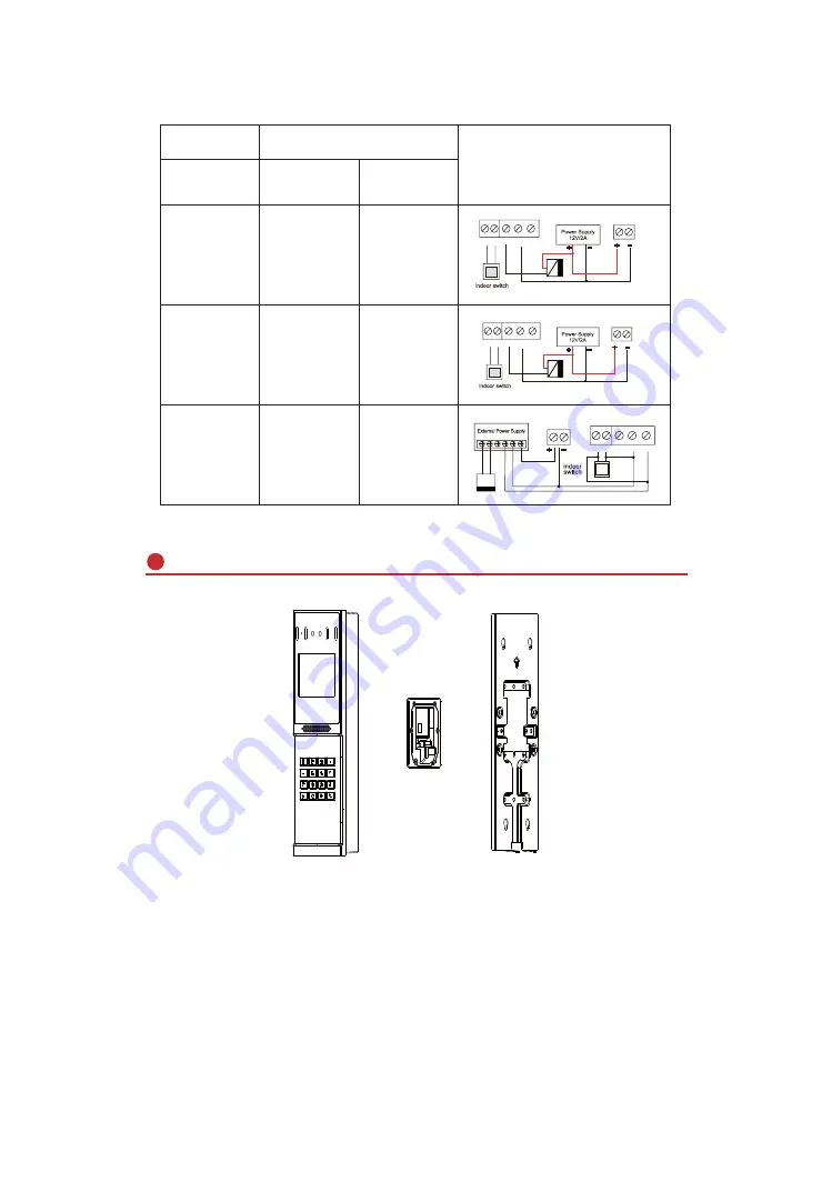
3) Wiring instructions
:
NO: Disconnected in idle state (normally open) ;
COM: Relay contact (common) ;
NC: Connected in idle state (normally closed)
Power Supply
For Lock
Electric-lock Mode
External
Power off and
open the door
Power on and
open the door
ɭ
ɭ
ɭ
ɭ
ɭ
ɭ
Wiring
S-I S-O
Electric lock (NO: normally open)
Power off and open the door
NC COM NO
S-I S-O NC COM NO
NC COM NO PUSH GNB 12V
Electric lock (NC: normally closed)
Power on and open the door
S-I S-O NC COM NO
Electric lock drive
(external power supply)
Electric lock drive
(external power supply)
Access control
power input
Access control
power input
Access control
power input
Installation Diagram
Figure 3-1
The three parts of the i66,
Wall mounting
:
Step 1: Installation preparation
A.Check the following contents:
KM3*30 screw x3
TA4 x 30mm screw x5
ijPPVFUHZDQFKRU[
KM4*30 screw x3
TM6#*20/screw x5
KM3*6mm screw x3
KB2.6*5 screw x1
B.Tools required for installation
The special L-shaped Torx screw tool provided with the product
Ph2 or Ph3 Phillips screwdriver, hammer, RJ45 crimping pliers
Wall drilling impact drill, 8mm impact drill x1
Figure 3-1


