background image

Life in evolution

43

8590A  8590B

OLTRE

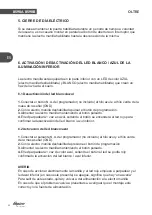
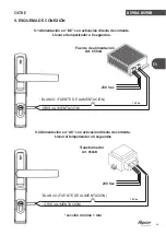
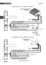
5. CIERRE DE DÍA ELÉCTRICO

Si se desea mantener la puerta habilitada durante un período de tiempo a voluntad 

del usuario, es necesario montar en paralelo al botón de abertura un interruptor que 

mantiene la electro manilla habilitada hasta la desconexión de la misma.

6. ACTIVACIÓN / DESACTIVACIÓN DEL LED BLANCO / AZUL DE LA

ILUMINACIÓN INFERIOR

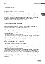
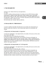
La electro manilla está equipada en la parte inferior con un LED de color AZUL 

(electro manilla deshabilitada) y BLANCO (electro manilla habilitada) que crean un 

haz de luz hacia el suelo.

6.1 Desactivación del led blanco/azul

1

.Conectar el botón N.A. del programador (no incluido) al hilo azul e al hilo verde de la

masa de la señal (GND).

2.

Con la electro manilla deshabilitada pulsar el botón de programación.

3

.Alimentar la electro manilla manteniendo el botón pulsado.

4

.El led parpadeará 1 vez en azul, soltando el botón se encenderá el led rojo para

confirmar la desactivación del led blanco / azul inferior.

6.2 Activación del led blanco/azul

1

.Conectar el pulsante N.A. del programador (no incluido) al hilo azul y el hilo verde

de la masa señal (GND).

2.

Con la electro manilla deshabilitada presione el botón de programación.

3.

Alimentar la electro manilla manteniendo el botón pulsado.

4.

El led parpadeará 1 vez de color azul, soltando el botón el led se podrá rojo

confirmado la activación del led blanco / azul inferior.

AVERIA

En caso de accionar eléctricamente la manilla y el led rojo empieza a parpadear y el 

led azul inferior (en caso este presente) se apague, significa que hay “una averia“.

Para salir de este estado, quitar y volver a dar alimentación a la electro manilla.

En caso de que el problema vuelva a presentarse, averiguar que el montaje esté 

correcto y/o la fuente de alimentación.

8590A  8590B

ES

Summary of Contents for OLTRE

Page 1: ...Life in evolution OLTRE Art 8590A Art 8590B ELETTROMANIGLIA ELECTRIC HANDLE ELECTRO POIGNEE ELECTRO MANILLA IT EN FR ES RUS 1 13 25 37 49 UGQU Rev 02...

Page 2: ...el led bianco blu 7 6 2 Abilitazione del led bianco blu 7 7 SOSTITUZIONE DEL CILINDRO 8 8 ESEMPI DI INSTALLAZIONE 9 8 1 Elettromaniglia con Oltre Bar e Pad 9 8 2 Elettromaniglia con Oltre Push 9 9 SCH...

Page 3: ...00 mA CORRENTE DI MANTENIMENTO I max TEMPORIZZAZIONE Regolabile da 0 60 secondi SEGNALAZIONE ESTERNA OPEN COLLECTOR ILLUMINAZIONE INFERIORE BIANCA BLU FERMO A GIORNO Meccanico e Elettrico Maniglia Dis...

Page 4: ...Utilizzando la chiave si pu abilitare meccanicamente l elettromaniglia Per abilitare tramite la chiave il fermo a giorno meccanico necessario togliere il grano che ne impedisce la completa rotazione v...

Page 5: ...ori di fissaggio presenti sul maniglione antipanico Accorciare il quadro d azionamento in dotazione e le viti di fissaggio Inserire il quadro d azionamento all interno del nottolino dell elettromanigl...

Page 6: ...viti precedentemente portate a misura Assicurarsi che le parti in movimento siano libere e non urtino parti dell infisso o vadano in contrasto con i meccanismi del maniglione Assicurarsi che durante i...

Page 7: ...maniglia fili grigio e bianco 3 L elettromaniglia si presenta con il led di colore rosso Premere il pulsante di programmazione fino al cambiamento di colore del led in blu Rilasciare immediatamente il...

Page 8: ...maniglia mantenendo il pulsante premuto 4 Il led lampegger 1 volte di colore blu rilasciando il pulsante il led diventer rosso confermando la disattivazione del led bianco blu di illuminazione inferio...

Page 9: ...Estrarre il cilindro Spostare il grano dal vecchio cilindro al nuovo cilindro Reinserire il cilindro Avvitare la vite bloccaggio cilindro L elettromaniglia predisposta per il montaggio di un mezzo ci...

Page 10: ...8 ESEMPI DI INSTALLAZIONE 8 1 Elettromaniglia con Oltre Bar e Pad 8 2 Elettromaniglia con Oltre Push Life in evolution IT 9 8590A 8590B OLTRE 8590A 8590B...

Page 11: ...rtare la temporizzazione a 0 secondi Alimentatore Art 8594A 230 Vac BIANCO ALIMENTAZIONE 12 Vdc GRIGIO ALIMENTAZIONE 9 2 Alimentazione in AC con attivazione diretta di corrente Portare la temporizzazi...

Page 12: ...Vdc GRIGIO ALIMENTAZIONE ROSSO VERDE NON ALIMENTARE AZZURRO POSITIVO ALIMENTAZIONE ARANCIONE OPEN COLLECTOR 12 Vdc MAX 30mA 9 4 Alimentazione in AC e apertura con contatto Trasformatore Art 8594B 230...

Page 13: ...Collegamento Elettromaniglia su impianto citofono Alimentatore Art 8594A 230 Vac BIANCO ALIMENTAZIONE 12 Vdc GRIGIO ALIMENTAZIONE ROSSO VERDE AZZURRO ARANCIONE OPEN COLLECTOR COM N A MODULO RELE 12Va...

Page 14: ...e blue LED 19 6 2 Activation of the white blue LED 19 7 REPLACEMENT OF THE CYLINDER 20 8 INSTALLATION EXAMPLES 21 8 1 Electric handle with OLTRE Bar and Pad 21 8 2Electric handle with OLTRE Push 21 9...

Page 15: ...s EXTERNAL INDICATOR OPEN COLLECTOR WHITE BLUE LOWER LIGHTING DOGGING DEVICE Mechanical and Electrical HANDLE SQUARE 9mm 700 mA 500 mA 500 mA Yes CYLINDER No The electric handle can be fitted with OLT...

Page 16: ...lit washer Grower The electric handle can be mechanically enabled with the key To activate the mechanical dogging device through the key remove the grub screw that prevents the complete rotation see f...

Page 17: ...he fixing holes of the panic bolt Shorten the operating spindle supplied and the fixing screws Insert the operating spindle inside the electric handle pawl Lock the spindle with the supplied grub scre...

Page 18: ...sembly tighten all the previously shortened screws Make sure the moving parts are free and do not hit parts of the door or hinder the panic bolt mechanisms Make sure the cable is not accidentally dama...

Page 19: ...wer supply grey and white wires 3The red LED of the electric handle is on Press the programming button until the LED becomes blue Release the programming button immediately The LED lights up for about...

Page 20: ...r supply keeping the button pressed 4 The blue LED will flash once and it will become red when the button is released confirming the white blue lower lighting LED deactivation 6 2 Activation of the wh...

Page 21: ...screw Pull the cylinder out Move the grub screw from the old to the new cylinder Insert the cylinder again Tighten the cylinder locking screw The electric handle is pre set for the assembly of a Euro...

Page 22: ...8 INSTALLATION EXAMPLES 8 1 Electric handle with OLTRE Bar and Pad 8 2 Electric handle with OLTRE Push Life in evolution 21 8590A 8590B OLTRE 8590A 8590B EN...

Page 23: ...ation Bring timer to 0 seconds Power supply unit Art 8594A 230 Vac WHITE POWER SUPPLY 12 Vdc GREY POWER SUPPLY Trasformer Art 8594B 230 Vac minimum cross section of 1 mm 8590A 8590B EN 9 2 AC power su...

Page 24: ...2 Vdc GREY POWER SUPPLY RED GREEN DO NOT POWER LIGHT BLUE POSITIVE POWER 12 Vdc MAX 30mA 9 4 AC power supply and opening by contact Trasformer Art 8594B 230 Vac minimum cross section of 1mm 8590A 8590...

Page 25: ...on of electric handle with intercom system Power supply unit Art 8594A 230 Vac 12 Vdc COM N A RELAY MODULE 12 Vac from INTERCOM minimum cross section of 1mm 8590A 8590B EN WHITE POWER SUPPLY GREY POWE...

Page 26: ...anches bleues 31 6 2 Activation des LEDS blanches bleues 31 7 REMPLACEMENT DU CYLINDRE 32 8 EXEMPLES D INSTALLATION 33 8 1 Electro poign e avec Oltre type Bar et Pad 33 8 2 Electro poign e avec Oltre...

Page 27: ...PORISATION R glable de 0 60 secondes SIGNALISATION EXTERNE OPEN COLLECTOR ECLAIRAGE PARTIE INFERIEURE BLANC BLU DISPOSITIFJOUR NUIT M canique ou Electrique CARRE DE POIGNEE 9mm 700 mA 500 mA 500 mA Ou...

Page 28: ...rnie avec le produit En utilisant la cl on peut activer l lectro poign e m caniquement Pour activer le dispositif jour nuit m canique par la cl enlever la vis sans t te qui en emp che la rotation comp...

Page 29: ...aux trous de fixage pr sents sur la barre anti panique Raccourcir le carr d actionnement fourni et les vis de fixage Ins rer le carr d actionnement l int rieur du cliquet de l lectro poign e Bloquer l...

Page 30: ...port es la mesure correcte S assurer que les parties en mouvement soient libres et qu elles ne heurtent pas des parties de la porte ou aillent en contraste avec les m canismes de la barre anti paniqu...

Page 31: ...nc 3 L lectro poign e se pr sente avec la LED rouge allum e Appuyer sur le bouton de programmation jusqu au passage de la LED la couleur bleue Rel cher imm diatem ent le bouton de programmation La LED...

Page 32: ...tenant le bouton appuy 4 La LED bleue clignotera une fois Apr s avoir rel ch le bouton la LED deviendra rouge en confirmant la d sactivation de la LED blanche bleue de l clairage inf rieur 6 2 Activat...

Page 33: ...e Enlever le cylindre D placer la vis sans t te du vieux au nouveau cylindre Repositionner le cylindre Visser la vis de blocage cylindre L lectro poign e est pr dispos e pour le montage d un demi cyli...

Page 34: ...8 EXEMPLES D INSTALLATION 8 1 Electro poign e avec Oltre type Bar et Pad 8 2 Electro poign e avec Oltre type Push Life in evolution 33 8590A 8590B OLTRE 8590A 8590B FR...

Page 35: ...nt Porter la temporisation 0 secondes Alimentateur Art 8594A 230 Vac BLANC ALIMENTATION 12 Vdc GRIS ALIMENTATION 9 2 Alimentation en AC avec activation directe de courant Porter la temporisation 0 sec...

Page 36: ...S ALIMENTATION ROUGE VERT NE PAS ALIMENTER BLEU CLAIR POSITIF ALIMENTATION ORANGE OPEN COLLECTOR 12 Vdc MAX 30mA 9 4 Alimentation en AC et ouverture par contact Transformateur Art 8594B 230 Vac 12Vac...

Page 37: ...chement Electro poign e un syst me d interphonie Alimentateur Art 8594A 230 Vac 12 Vdc COM N A MODULE RELAIS 12 Vac par INTERPHONE 8590A 8590B FR section minimum 1 mm BLANC ALIMENTATION GRIS ALIMENTAT...

Page 38: ...zul 43 6 2 Activaci n del led blanco azul 43 7 SUSTITUCI N DEL CILINDRO 44 8 EJEMPLO DE INSTALACI N 45 8 1 Electro manilla con antipanico Oltre Bar y Pad 45 8 2 Electro manilla con antipanico Oltre Pu...

Page 39: ...I max SINCRONIZACI N Regulable de 0 60 secondi SE AL EXTERNA SELECTOR ABIERTO ILUMINACI N INFERIOR BLANCA AZUL CIERRE DE D A Mec nico Y El ctrico Ambidestra CUADRADILLO MANILLA 9mm 700 mA 500 mA 500...

Page 40: ...dos Usando la llave se puede utilizar mec nicamente la electro manilla Para usar el cierre de d a es necesario eliminar el tornillo sin cabeza que bloquea la rotaci n completa ver figura En esta confi...

Page 41: ...de fijaci n presentes en el antip nico Aplicar el cuadro de accionamiento suministrado y los tornillos de fijaci n Inserte el panel de la unidad dentro del soporte el ctrico Solo si es necesario bloq...

Page 42: ...con los tornillos previamente ajustados Verificar que las partes m viles est n libres sin que bloquen parte del cerramiento o entren en conflicto con el mecanismo Verificar que durante el paso del cab...

Page 43: ...rde de la masa se al GND 2 Alimentar la electro manilla hilo gris y blanco 3 La electro manilla presenta el LED de color ROJO Presionar el pulsador de programaci n hasta el cambio de color del LED a A...

Page 44: ...limentar la electro manilla manteniendo el bot n pulsado 4 El led parpadear 1 vez en azul soltando el bot n se encender el led rojo para confirmar la desactivaci n del led blanco azul inferior 6 2 Act...

Page 45: ...dro Mover el tornillo sin cabeza del cilindro viejo al cilindro nuevo Insertar nuevamente el cilindro Aplicar los tornillos para bloquear el cilindro La electro manilla est predispuesta para la aplica...

Page 46: ...8 EJEMPLO DE INSTALACI N 8 1 Electro manilla con antipanico Oltre Bar y Pad 8 2 Electro manilla con antipanico Oltre Push Life in evolution 45 8590A 8590B OLTRE 8590A 8590B ES...

Page 47: ...orizador a 0 segundos Fuente de alimentaci n Art 8594A 230 Vac BLANCO FUENTE DE ALIMENTACI N 12 Vdc GRIS ALIMENTACI N 9 2 Alimentaci n en AC con activaci n directa de corriente Llevar el temporizador...

Page 48: ...Vac BLANCO ALIMENTACI N 12 Vdc GRIS ALIMENTACI N ROJO VERDE NO ALIMENTAR AZUL CLARO NARANJA COLECTOR ABIERTO 12 Vdc MAX 30mA 9 4 Alimentaci n en AC y abertura con contacto Transformador Art 8594B 230...

Page 49: ...Electro Manilla a un sistema de interfono Fuente de alimentaci n Art 8594A 230 Vac 12 Vdc COM N A M DULO RELE 12 Vac del TEL FONO sezione minima 1 mm 8590A 8590B ES BLANCO ALIMENTACI N GRIS ALIMENTAC...

Page 50: ...1 50 2 51 3 54 4 54 4 1 0 54 4 2 5 60 54 5 55 6 55 6 1 55 6 2 55 7 56 8 57 8 1 Bar 57 8 2 Push 57 9 58 9 1 0 58 9 2 0 58 9 3 59 9 4 59 9 5 60 Life in evolution 49 8590A 8590B OLTRE RUS...

Page 51: ...RUS Life in evolution 50 8590A 8590B OLTRE 1 8590A 8590B 9mm I 700 mA I 0 60 OPEN COLLECTOR 9mm 700 mA 500 mA 500 mA 0 60 push bar touch bar 12 24 12 12 24 12...

Page 52: ...Life in evolution 51 8590A 8590B OLTRE 2 Grower 1 2 8590A 8590B RUS...

Page 53: ...Life in evolution 52 8590A 8590B OLTRE 8590B 1 8 8590A 8590B RUS L 24 0 1 L 5 9 9...

Page 54: ...Life in evolution 53 8590A 8590B OLTRE 8590A 8590B RUS...

Page 55: ...Life in evolution 54 8590A 8590B OLTRE 3 8560 5 60 8561C 4 4 1 0 1 GND 2 3 5 60 1 GND 2 3 5 8590A 8590B RUS...

Page 56: ...Life in evolution 55 8590A 8590B OLTRE 5 6 6 1 1 GND 2 3 4 1 6 2 1 GND 2 3 4 1 8590A 8590B RUS...

Page 57: ...Life in evolution 56 8590A 8590B OLTRE 7 DIN 40 30 10 SILCA GVY1R 8590A 8590B RUS...

Page 58: ...8 8 1 Bar 8 2 Push Life in evolution 57 8590A 8590B OLTRE 8590A 8590B RUS...

Page 59: ...Life in evolution 58 8590A 8590B OLTRE 9 9 1 0 8594A 230 12 9 2 0 8594B 230 12 1 8590A 8590B RUS...
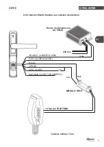
Page 60: ...Life in evolution 59 8590A 8590B OLTRE 9 3 230 12 OPEN COLLECTOR 12 MAX 30mA 9 4 230 12 8590A 8590B RUS 8594A 8594B 1 OPEN COLLECTOR...

Page 61: ...Life in evolution 60 8590A 8590B OLTRE 9 5 230 12 COM N A 12 8590A 8590B RUS 8594A 1 OPEN COLLECTOR...

Reviews: