©
FAR GROUP EUROPE
WARNING: Never release lever 2 until the thread cutting is finished
To reset the tool in the start position, reverse the chuck direction and repeat a number of
0.25 mm passes to achieve the final 1.3925 mm dimension, Try the M 20 x 2.5 bolt before
disengaging the centre gage lever 2
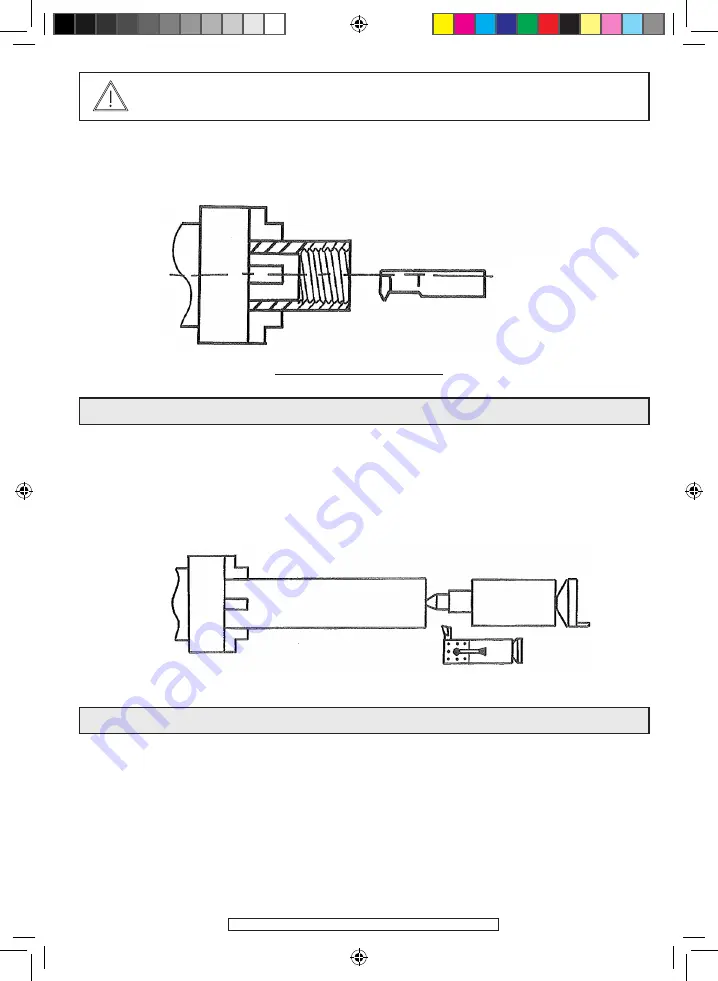
The mixed fitting mode is used when the part, once clamped in the chuck, protrudes
from it by more than twice its diameter.
Tighten the part in the chuck, Drill a centre hole using a centring bit, Then bring up
the tailstock centre (114317), the mounting is a rigid one and it is possible to safely ma-
chine.
The fitting between tailstocks mode is used to produce axes that require perfect concen-
tricity between all diameters. To do this, it is necessary to drill a centre hole through both
ends of the axis to be machined. Then take the chuck apart and fit the dry tailstock and
place the part to be milled between the dry tailstock and the spinning one (114317).
Drive is achieved with a toc
MIXED FITTING
FITTING BETWEEN TAILSTOCKS
OTHER MILLING MODES
Metric
threading
114135-Manual-D-EN.indd 22
21/03/12 10:45:00
Summary of Contents for TDM 400B
Page 5: ...FAR GROUP EUROPE SLAVED SAFETY CASING 114135 Manual D EN indd 5 21 03 12 10 44 23...
Page 13: ...FAR GROUP EUROPE 114135 Manual D EN indd 13 21 03 12 10 44 55...
Page 29: ...FAR GROUP EUROPE FAR GROUP EUROPE TDM 400B 114135 Manual D EN indd 29 21 03 12 10 45 06...
Page 30: ...FAR GROUP EUROPE TDM 400B 114135 Manual D EN indd 30 21 03 12 10 45 06...
Page 31: ...FAR GROUP EUROPE TDM 400B 114135 Manual D EN indd 31 21 03 12 10 45 06...
Page 32: ...FAR GROUP EUROPE TDM 400B 114135 Manual D EN indd 32 21 03 12 10 45 07...
Page 33: ...FAR GROUP EUROPE TDM 400B 114135 Manual D EN indd 33 21 03 12 10 45 07...
Page 34: ...FAR GROUP EUROPE TDM 400B 114135 Manual D EN indd 34 21 03 12 10 45 07...
Page 35: ...FAR GROUP EUROPE TDM 400B 114135 Manual D EN indd 35 21 03 12 10 45 08...
Page 36: ...FAR GROUP EUROPE TDM 400B 114135 Manual D EN indd 36 21 03 12 10 45 08...


