background image

I

Revisione - 03

Date 01-2011

61

KJ 45/S

KJ 45/S

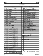
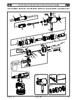
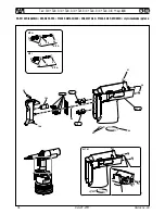
PARTI DI RICAMBIO

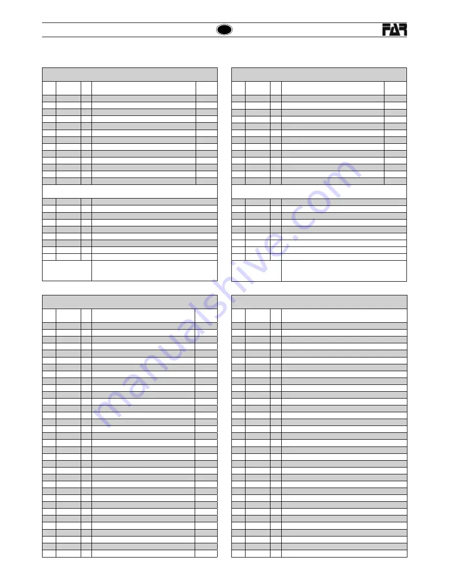
Tav.


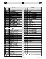
3/4

COD.

Qt.

DESCRIZIONE

KIT

61

710528

1

Guarnizione OR 008 DOWTY

62

710572

1

Guarnizione OR 2-120 PARKER (N674-70)

63

710385

2

Guarnizione OR 2-006 PARKER (N674-70)

64

713394

1

Guarnizione OR 2-106 PARKER (N674-70)

65

713401

1

Rullino NRB ø3x19.8

66

710376

2

Guarnizione OR 2-009 PARKER (N674-70)

68

711338

2

Guarnizione OR-2-003 PARKER (N674-70)

A - H - I

69

710918

2

Guarnizione OR-2-005 PARKER (N674-70)

A - H - I

70

716060

4

Guarnizione OR 2-010 PARKER (N674-70)

A - H - I

108 71345648

1

Pulsante di comando

109 71345649

1

Pulsante svitamento

KIT

KIT H 74000033

1

Kit pistone superiore

KIT I 74000034

1

Kit pistone inferiore

KIT L 74000035

1

Kit piastra di ritegno

KIT M 74000053

1

Kit impugnatura

KIT

Indica che il particolare vie ne ven du to in Kit com po sti da 
particolari diversi in quan ti tà diverse.

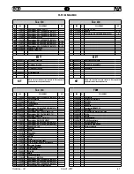
Tav. 4/4

COD.

Qt.

DESCRIZIONE

KIT

70

716060

1

Guarnizione OR 2-010 PARKER (N674-70)

A - H - I

71 72C00017

1

Corpo completo

72

713403

1

Sfera ø5.5

73

71345272

1

Tappo valvola

74

71345273

1

Spoletta

75

713400

7

Guarnizione OR-5-616 PARKER (N674-70)

76 72A00028

1

Raccordo aria 1/4 GAS

77 71C00355

1

Guarnizione OR 1.78x8.73 (N674-70)

78 71C00356

1

Guarnizione OR 1.78x7.66 (N674-70)

79

713304

1

Raccordo guida stelo

80

711827

1

Guarnizione TS 12 - 19 - 5,7 / L

81

710390

1

Guarnizione BALSELE B 075047

82 71C00522

1

Guarnizione OR-5-615 PARKER (N674-70)

83

710914

1

Guarnizione OR-2-116 PARKER (N552-90)

84

713319

1

Dado M22 X 1.25

85

713320

1

Raccordo

86

713315

1

Stelo

87

713197

1

Coperchio

88

713194

1

Pomello

89

713316

1

Ghiera

90

713191

1

Disco

91

712575

1

Vite TSEI M5X12 UNI 5933

92

713404

4

Vite TSP autof. ø2.5x12 per plastica

93

713317

1

Raccordo fl angiato

94

713318

1

Albero trascinatore

95

713321

1

Vite 2 principi

96

713322

1

Vite M5

97

713199

1

Molla

98

713196

1

Fondello antiurto

99

713434

1

Seeger ø 11 UNI 7435

100 71C00297

2

Guarnizione OR 6-700 PARKER (N674-70)

101

713398

1

Guarnizione OR-2-340 PARKER (N674-70)

102

710350

1

Guarnizione OR 2-109 PARKER (N674-70)

103 72B00021

1

Gruppo valvola di sovrapressione

Tav. 4/4

COD.

Qt.

DESCRIZIONE

KIT

104 71C00305

1

Ghiera 1/4 GAS

105

713192

5

Gabbia

A - P

106

713271

2

Guarnizione OR 2-014 PARKER (674-70)

A

KIT

KIT N 74000030

1

Kit pistone pneumatico

KIT O 74000031

1

Kit camicia pneumatica

KIT P 74000023

1

Kit spoletta

KIT

Indica che il particolare vie ne ven du to in Kit com po sti da 
particolari diversi in quan ti tà diverse.

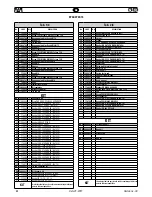
F001

COD.

Qt.

DESCRIZIONE

1

71C00764

1

Cuscinetto

2

71345645

1

Portasatelliti estremo

3

71345644

3

Satellite

4

71345643

1

Corona

5

71345642

1

Rondella

6

71C00763

1

Cuscinetto ADR AYZ C2

7

71345640

1

Raccordo

8

71C00761

2

Spina elastica UNI 6875 ø1,5x10

9

71345639

5

Aletta

10

71345638

1

Rotore

11

71345637

1

Corpo esterno

12

71345641

1

Piattello posteriore

13 71C00794

1

Rullino INA ø2x9,8

14 71C00762

1

Cuscinetto JESA 695-ZZ

A

72A00125

1

Motore completo

Summary of Contents for KJ 45/S

Page 1: ...E A SERTIR OLEOPNEUMATIQUE POUR INSERTS M4 M12 MODE D EMPLOI PIECES DETACHEES BERSETZUNG VON ORIGINALANLEITUNGEN PNEUMATISCH HYDRAULISCHES NIETWERKZEUG F R BLINDNIETMUTTERN M4 M12 BEDIENUNGSANLEITUNG...

Page 2: ...ons successives La personne autoris e constituer le dossier technique est Giacomo Generali chez FAR S r l avec si ge Quarto Inferiore BO Via Giovanni XXIII n 2 DieUnterzeichnete Fa FarS r l mitSitzinQ...

Page 3: ...UCTIONS FOR USE 12 MODE D EMPLOI 20 BEDIENUNGSANLEITUNG 28 INSTRUCCIONES DE USO 36 INSTRUKCJA OBS UGI 44 A 52 PARTI DI RICAMBIO 60 SPARE PARTS 62 PIECES DETACHEES 64 ERSATZTEILE 66 PIEZAS DE REPUESTO...

Page 4: ...o concepito La garanzia non valida se l attrezzo non viene utilizzato e se non viene sottoposto a manutenzione come specificato nel manuale di istruzione e manutenzione In caso di difetti o guasti la...

Page 5: ...dite dal sistema oleodinamico sono precluse dall impiego di guarnizioni a tenuta che eliminano questo problema DATI TECNICI Pressione di esercizio 6 7 BAR Diametro interno minimo tubo alimentazione ar...

Page 6: ...na B montato sulla rivettatrice in confezione corrisponde ad una filettatura di M10 Primadiutilizzarelarivettatriceedopoognicambiodiformato occorreregolarelacorsainfunzionedelledimensioni deltipo di i...

Page 7: ...con la testina B verificando che il tirante A fuoriesca di 2mm dall inserto In caso di ulteriore regolazione del tirante A procedere come riportato a pag 10 E possibile ora procedere alla messa in pos...

Page 8: ...verificano condizioni per le quali sia necessarioottenereunosvitamentoforzatodeltirantefilettato dall inserto premere il pulsante P ATTENZIONE Eseguire questa operazione trattenendo saldamente la riv...

Page 9: ...sollevandolo f10 Dopo aver preparato il tirante filettato A della misura desiderata disporreesostenereicomponenticomeinf11 ed eseguire il montaggio assicurandosi che i particolari siano correttamente...

Page 10: ...esiderata sul tirante filettato fino a che la testa dell inserto vada in battuta con la testina B della rivettatrice La testina B regolata correttamente se il tirante filettato fuoriesce per circa 2 m...

Page 11: ...osito contenitore e avvalersi sucessivamente di una ditta autorizzata allo smaltimento dei rifiuti MANUTENZIONE Manutenzione giornaliera Controllare che il tirante filettato non sia danneggiato Contro...

Page 12: ...the machine should be completely overhauled GUARANTEE AND TECHNICAL ASSISTANCE FAR riveting tools are covered by a 12 months guarantee The period of guarantee starts from the date of delivery specifi...

Page 13: ...m are eliminatedbysomesealedgaskets whichsolvethisproblem TECHNICAL DATA Working pressure 6 7 BAR Min int diam of the compressed air feeding hose 8 mm Max free air consumption per cycle 9 nl Maximum f...

Page 14: ...led on this riveting tool corresponds to a M10 thread Beforeusingtherivetingtoolandaftereachchangeofsize the stroke should be adjusted according to the dimensions type of the insert and thickness of t...

Page 15: ...Makesurethattheinsertheadtouches the head B checking that the tie rod A comes out of 2mm from the insert In case of further adjustments of the tie rod A follow the instructions of page 18 It is now p...

Page 16: ...PROBLEMS fig f7 Any time it is necessary to unscrew forcedly the threaded tie rod from the insert push the button P ATTENTION Carry out this operation keeping the riveting tool firmly in order to avoi...

Page 17: ...panner f9 Extract the threaded tie rod pushing and lifting it at the same time f10 After preparing the threaded tie rod A of the size you need arrange and keep the components as shown in f11 and assem...

Page 18: ...sert of the desired length on the threaded tie rod manually until the insert head touches the riveting tool head B The head is adjusted correctly if the threaded tie rod comes out of the insert screwe...

Page 19: ...ustputtheoilinasuitablecontainerandcontactacompany authorized to dispose of wastes MAINTENANCE Daily maintenance Check that the threaded tie rod is not damaged Check the supply system of the compresse...

Page 20: ...estpasvalidesil outiln estpasutilis ou s iln estpasentretenucommeindiqu danslemoded emploi En cas de d faut ou autre anomalie FAR S r l s engage uniquement r parer ou changer selon son choix les pi ce...

Page 21: ...imin s par l utilisation de joints haute r sistance CARACTERISTIQUES TECHNIQUES Pression de service 6 7 BAR Diam tre interne minimum tuyau d alimentation air comprim 8 mm Consommation air max par cycl...

Page 22: ...est un filetage M10 Avant d utiliser la riveteuse et apr s chaque changement de format il est n cessaire de r gler la course en fonction des dimensions du format de l insert et de l paisseur du mat r...

Page 23: ...e B en s assurant que le tirant A d passe de l insert de 2 mm En cas de nouveau r glage du tirant A proc der comme indiqu page 26 Il est pr sent possible de proc der la pose de l insert en appuyant su...

Page 24: ...7 Lorsqu ilestn cessaired obtenirund vissageforc dutirant filet de l insert il faut appuyer sur le bouton P ATTENTION Effectuer cette op ration en tenant fermement la riveteuse de fa on viter les mouv...

Page 25: ...f10 Apr s avoir pr par le tirant A de la dimension d sir e soutenir les composants comme indiquer dans le f11 et ex cuter la mise en place s assurer que l ensemble des composants soit correctement cen...

Page 26: ...la longueur voulue sur le tirant filet jusqu ce que la t te de l insert soit en but e contre la t te B de la riveteuse La t te est correctement r gl e si le tirant d passe d environ 2 mm l insert viss...

Page 27: ...nt et la remettre un centre agr de collecte des d chets ENTRETIEN Entretien quotidien s assurer que le tirant filet n est pas endommag contr ler le syst me d alimentation d air comprim s assurer que l...

Page 28: ...wird Die Garantie ist nicht g ltig wenn das WerkzeugnichtinderimBedienungs undWartungsanleitung spezifizierten Weise gewartet und bedient wird BeiM ngelnoderFehlernistdieFARS r l nurverpflichtet die f...

Page 29: ...Sabsoluthandlich DieM glichkeiteneinerUndichtheit von l aus dem ldynamischen System werden durch die Verwendung von undurchl ssigen Dichtungen verhindert die dieses Problem eliminieren TECHNISCHE DAT...

Page 30: ...einem M10 Gewinde Vor der Verwendung der Nietmaschine und nach jedem Dimensionswechsel ist der Hub gem Abmessungen Typ von Blindnietmutter und St rke des zu befestigenden Materials einzustellen Drehe...

Page 31: ...hlagmitdemMundst ck B liegt indemSie pr fen ob der Gewindedorn A um 2 mm aus der Blindnietmutter hervorsteht Bei einer weiteren Einstellung des Gewindedornes A gehen Sie wie auf Seite 34 wiedergegeben...

Page 32: ...s n tig ist den Gewindedorn aus dem Blindnietmutter gezwungen abzuschrauben dr cken Sie den Knopf P ACHTUNG F hrenSiediesenVorgangaus indemSie die Nietmaschine ganz fest halten sodass m gliche ruckart...

Page 33: ...andels blichen 22 mm Schl ssel abschrauben Abb f9 Den Gewindedorn schieben und gleichzeitig heben um ihn herauszuziehen Die Teile gem Abb f11 stellen und halten und den ausgew hlten Gewindedorn A mont...

Page 34: ...dedorn bis der Blindnietmutterkopf bis Anschlag mit dem Mundst ck B der Nietmaschine liegt Das Mundst ck ist korrekt eingestellt wenn der Gewindedorn um zirka 2 mm aus der auf diesem verschraubten Bli...

Page 35: ...ungdes ldynamischen Kreises das gesamte l in einem besonderen Beh lter auf und wenden Sie anschlie end zur Entsorgung an eine Fachfirma WARTUNG T gliche Wartung Pr fen Sie dass der Gewindedorn nicht b...

Page 36: ...ual de instrucci n y manutenci n En caso de defectos o aver as la FAR S r l se empe a s lo en reparar y o sustituir los componentes que ella misma considera defectuosos ADVERTENCIAS Y MEDIDAS DE SALVA...

Page 37: ...le Las posibilidades de perdida por el sistema oleodin mico son eliminadas con el uso de juntas que eliminan este problema DATOS T CNICOS Presi n de trabajo 6 7 BAR Di metro interno m nimo tubo alimen...

Page 38: ...B ensemblado en el embalaje de la remachadora corrisponde al fileteado M10 Antes de emplear la remachadora y despu s de cada cambio de formato hay que regular la carrera seg n las dimensiones el forma...

Page 39: ...ado Asegurarse que la cabeza de la tuerca toque la cabeza B averiguando que el tirante A salga de 2mm de la tuerca En caso de regulaci n adicional del tirante A actuar como indicado en p g 42 Ahorasep...

Page 40: ...ENTO fig f7 En todos los casos donde se necesita destornillar de manera forzadaeltiranteroscadodelatuerca apretarelpulsador P ATENCI N Efectuar esta operaci n teniendo firmemente la remachadora de man...

Page 41: ...ave comercial de mm 22 f9 remover el tirante fileteado empujarlo y entretanto levantarlo f10 despues la preparaci n del tirante fileteado A de la medida querida colocar y sostener los componentes como...

Page 42: ...gitudqueridasobre el tirante fileteado manualmente hasta que la cabeza de la tuerca toque la cabeza B de la remachadora La cabeza es ajustadacorrectamentesieltirantefileteadosaledelatuerca atornillado...

Page 43: ...autorizada para la eliminaci n de desechos MANUTENCI N Manutenci n diaria Controlarqueeltirantefileteadonoseencuentreestropeado Controlar el sistema de alimentaci n del aire comprimido Controlar que l...

Page 44: ...gosprzedawcyFAR Gwarancja wygasaje liurz dzenieniejestu ywanelubje liniejestkonserwowanewspos b opisany w instrukcji obs ugi i konserwacji W przypadku stwierdzenia wady fabrycznej produktu firma FAR z...

Page 45: ...emuszczelniaczyeliminuje mo liwo spadku mocy zacisku DANETECHNICZNE Ci nienie robocze 6 7 BAR Minimalna rednica wewn przewodu zasilania 8 mm Zu ycie maks powietrza na cykl 9 nl Si a maksymalna 6 5 BAR...

Page 46: ...Je eli tak nie jest wymieniamy je na dan rednic Zesp trzpie gwintowany A g owica B zamontowany na nitownicy w opakowaniu posiada gwint M10 Po ka dej wymianie trzpienia na inn rednic upewniamy si e re...

Page 47: ...si automatycznie rys f4 Upewniamy si e ko nierz nitonakr tkistykasi zkraw dzi g owicy B i etrzpie wystajeznitonakr tki na ok 2 mm A Wtymmomenciemozemyprzystapicdomontazunitonakretkitrzymajacwcisniety...

Page 48: ...ICY rys f7 Wprzypadku gdyzachodzipotrzebawymuszonegowykr caniagwintowanego trzpienia z nitonakr tki nale y wcisn przycisk P UWAGA Powy sz czynno wykonujemymocnotrzymaj c nitownic wprzeciwnymraziejejgw...

Page 49: ...za 22 mm f9 Wyj trzpie gwintowany popychaj cgoir wnocze nieunosz cgodo g ry f10 Przygotowawszy gwintowany trzpie A o danym rozmiarze nale y rozmie ci poszczeg lne elementy tak jak to pokazano na rys f...

Page 50: ...cznie nakr camy nitonakr tk na gwintowany trzpie tak aby ko nierz nitonakr tki dotyka kraw dzi g owicy B Pozycja g owicy jest prawid owa je eli trzpie wychodzi z nitonakr tki na ok 2 mm Wprzeciwnymra...

Page 51: ...us ugfirmyupowa nionej do usuwania odpad w KONSERWACJA Konserwacja codzienna sprawdzamy czy gwintowany trzpie nie jest uszkodzony sprawdzamy instalacj zasilania powietrzem sprawdzamyczysi azaciskujest...

Page 52: ...RUS KJ 45 S KJ 45 S Date 01 2011 Revisione 03 52 A I 52 52 53 53 53 53 54 54 55 56 57 58 59 59 59 FAR s r l FAR s r l CEE 85 374 http www far bo it Far 12 FarS r l A 70 A...

Page 53: ...Revisione 03 Date 01 2011 53 RUS KJ 45 S KJ 45 S KJ45 S CE 4 12 KJ45 S KJ45 S 6 7 8 9 6 5 27440 10 2 860 5 50 Ac 2 5 m s2 20 C A 74 dBA C 130 dBC A 86 dBA 10 A B C D E F G H I L M N O P Q...

Page 54: ...RUS KJ 45 S KJ 45 S Date 01 2011 Revisione 03 54 f1 6 6 5 f1 1 2 3 4 5 F 7 F 53 FRL f2 f3 57 10 h 55 N f3 58 N f2 1 2 4 5 3 3 m Max f1 F Q Q Q...

Page 55: ...11 55 RUS KJ 45 S KJ 45 S f3 M 2 mm 0 M 0 4 mm 1 M 8 mm 15 0 1 2 3 4 5 6 7 9 8 10 11 12 13 14 15 M12 1 4 M4 0 3 4 M5 0 5 5 M8 0 8 6 M10 1 6 M12 1 7 M6 0 5 6 f4 f5 f6 f2 f3 f4 2 58 D fig f5 P fig f7 f2...

Page 56: ...RUS KJ 45 S KJ 45 S Date 01 2011 Revisione 03 56 f7 P f7...

Page 57: ...Revisione 03 Date 01 2011 57 RUS KJ 45 S KJ 45 S f8 f9 f10 f11 6 A B R M4 M6 S f8 O 22 f9 f10 A f11 f11 R O 22 M8 M12 M4 M6 A R B A R B S f8 22 mm O f11 f10 f9...

Page 58: ...RUS KJ 45 S KJ 45 S Date 01 2011 Revisione 03 58 f14 f15 f16 2 22 A B C B f15 f16 f14 22 mm C...

Page 59: ...Revisione 03 Date 01 2011 59 RUS KJ 45 S KJ 45 S f17 f18 I 4 T PANOLIN HLP ISO 32 D T T 54 55 54 7 f18 600 000 FAR s r l I 5 8 PANOLINHLPISO32 DIN 51524 2 HLP f17 f18...

Page 60: ...78 71C00356 1 Guarnizione OR 1 78x7 66 N674 70 82 71C00522 1 Guarnizione OR 5 615 PARKER N674 70 83 710914 1 Guarnizione OR 2 116 PARKER N552 90 100 71C00297 2 Guarnizione OR 6 700 PARKER N674 70 101...

Page 61: ...47 82 71C00522 1 Guarnizione OR 5 615 PARKER N674 70 83 710914 1 Guarnizione OR 2 116 PARKER N552 90 84 713319 1 Dado M22 X 1 25 85 713320 1 Raccordo 86 713315 1 Stelo 87 713197 1 Coperchio 88 713194...

Page 62: ...Gasket OR 1 78x7 66 N674 70 82 71C00522 1 Gasket OR 5 615 PARKER N674 70 83 710914 1 Gasket OR 2 116 PARKER N552 90 100 71C00297 2 Gasket OR 6 700 PARKER N674 70 101 713398 1 Gasket OR 2 340 PARKER N...

Page 63: ...ket OR 5 615 PARKER N674 70 83 710914 1 Gasket OR 2 116 PARKER N552 90 84 713319 1 Nut M22 X 1 25 85 713320 1 Connector 86 713315 1 Stem 87 713197 1 Cover 88 713194 1 Knob 89 713316 1 Ring nut 90 7131...

Page 64: ...e OR 1 78x7 66 N674 70 82 71C00522 1 Garniture OR 5 615 PARKER N674 70 83 710914 1 Garniture OR 2 116 PARKER N552 90 100 71C00297 2 Garniture OR 6 700 PARKER N674 70 101 713398 1 Garniture OR 2 340 PA...

Page 65: ...ture OR 5 615 PARKER N674 70 83 710914 1 Garniture OR 2 116 PARKER N552 90 84 713319 1 Ecrou M22 X 1 25 85 713320 1 Raccord 86 713315 1 Tige 87 713197 1 Couvercle 88 713194 1 Bouton 89 713316 1 Embout...

Page 66: ...73 N674 70 78 71C00356 1 Dichtung OR 1 78x7 66 N674 70 82 71C00522 1 Dichtung OR 5 615 PARKER N674 70 83 710914 1 Dichtung OR 2 116 PARKER N552 90 100 71C00297 2 Dichtung OR 6 700 PARKER N674 70 101...

Page 67: ...15 PARKER N674 70 83 710914 1 Dichtung OR 2 116 PARKER N552 90 84 713319 1 Mutter M22 X 1 25 85 713320 1 Anschlusst ck 86 713315 1 Schaft 87 713197 1 Dekel 88 713194 1 Knopf 89 713316 1 Nutmutter 90 7...

Page 68: ...7 71C00355 1 Junto OR 1 78x8 73 N674 70 78 71C00356 1 Junto OR 1 78x7 66 N674 70 82 71C00522 1 Junto OR 5 615 PARKER N674 70 83 710914 1 Junto OR 2 116 PARKER N552 90 100 71C00297 2 Junto OR 6 700 PAR...

Page 69: ...5 PARKER N674 70 83 710914 1 Junto OR 2 116 PARKER N552 90 84 713319 1 Tuerca M22 x 1 25 85 713320 1 Empalme 86 713315 1 Vastago 87 713197 1 Tapon 88 713194 1 Perilla 89 713316 1 Virola 90 713191 1 Di...

Page 70: ...8x7 66 N674 70 82 71C00522 1 Gasket OR 5 615 PARKER N674 70 83 710914 1 Gasket OR 2 116 PARKER N552 90 100 71C00297 2 Gasket OR 6 700 PARKER N674 70 101 713398 1 Gasket OR 2 340 PARKER N674 70 102 710...

Page 71: ...Uszczelka OR 2 116 P N 552 90 84 713319 1 Nakr tka M22x1 25 85 713320 1 Przy cze 86 713315 1 T ok 87 713197 1 Pokrywa korpusu 88 713194 1 Pokr t o 89 713316 1 Pier cie 90 713191 1 Tarcza pokr t a 91...

Page 72: ...R N674 70 75 713400 7 OR 5 616 PARKER N674 70 77 71C00355 1 OR 1 78x8 73 N674 70 78 71C00356 1 OR 1 78x7 66 N674 70 82 71C00522 1 OR 5 615 PARKER N674 70 83 710914 1 OR 2 116 PARKER N674 70 100 71C002...

Page 73: ...1827 1 TS 12 19 5 7 L 81 710390 1 BALSELE B 0750471 82 71C00522 1 OR 5 615 PARKER N674 70 83 710914 1 OR 2 116 PARKER N674 70 84 713319 1 22 1 25 85 713320 1 86 713315 1 87 713197 1 88 713194 1 89 713...

Page 74: ...8 5 12 16 20 19 15 11 107 6 3 21 24 17 13 KIT A 22 KIT Q 2 23 9 8 7 6 NOTA ancora possibile montare NOTE It is still possible to assemble NOTE Vous pouvez toujours monter HINWEIS Es ist noch m glich z...

Page 75: ...PARTS PIECES DETACHEES ERSATZTEILE PIEZAS DE REPUESTO CZ CIZAMIENNE 49 39 35 34 37 59 28 30 27 54 40 58 53 53 48 26 29 36 38 32 31 KIT F KIT D KIT C KIT E 57 56 55 43 42 44 41 KIT D 51 50 KIT C KIT F...

Page 76: ...6 PARTI DI RICAMBIO SPARE PARTS PIECES DETACHEES ERSATZTEILE PIEZAS DE REPUESTO CZ CIZAMIENNE 61 62 63 64 70 KIT H KIT M KIT I 66 KIT H KIT I KIT L 68 KIT A 69 70 68 KIT A 69 KIT M 65 108 109 Tav 3 4...

Page 77: ...TS PIECES DETACHEES ERSATZTEILE PIEZAS DE REPUESTO CZ CIZAMIENNE KIT N KIT P 86 82 80 81 83 79 75 75 70 89 91 90 71 76 103 105 77 78 106 99 100 102 84 100 96 101 73 74 93 95 94 97 72 88 92 87 98 85 KI...

Page 78: ...KJ 45 S KJ 45 S Date 01 2011 Revisione 03 78 PARTI DI RICAMBIO SPARE PARTS PIECES DETACHEES ERSATZTEILE PIEZAS DE REPUESTO CZ CIZAMIENNE F001 1 6 11 8 12 13 14 7 8 9 10 2 3 4 5...

Page 79: ......

Page 80: ...imede 8 Tel 39 02 2409634 Fax 39 02 26222279 E mail itacom far bo it L elenco dei centri di assistenza disponibile sul Ns sito web http www far bo it Organizzazione The list of the service centres is...

Reviews: