background image

E

69

KJ 45

KJ 45

Revision - 04

Date 10-2008

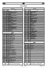
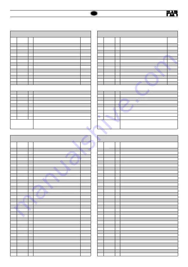
PIEZAS DE REPUESTO

Tab. 3/4

CODIGO

C.dad

DESCRIPCIÓN

KIT

61

710528

1

Junto OR 008 DOWTY 

62

710572

1

Junto OR-2-120 PARKER (N674-70)

63

710385

2

Junto OR 2-006 PARKER(N674-70)

64

713394

1

Junto OR 2-106 PARKER(N674-70)

65

713401

1

Rodillo NRB diam.3x19.8

66

710376

2

Junto OR-2-009 PARKER (N674-70)

67

72A00019

1

Unidad pulsador

68

711338

2

Junto OR-2-003 PARKER (N674-70)

A - H - I

69

710918

2

Junto OR 2-005 PARKER(N674-70)

A - H - I

70

716060

4

Junto OR 2-010 PARKER(N674-70)

A - H - I

KIT

KIT H

74000033

1

Kit piston superior

KIT I

74000034

1

Kit piston inferior

KIT L

74000035

1

Kit placa de retencion

KIT M

74000036

1

Kit empuñadura

KIT

Indica que la pieza se ven de en juegos formados por piezas 
distintas en cantidades distintas.

Tab. 4/4

CODIGO

C.dad

DESCRIPCIÓN

KIT

70

716060

1

Junto OR 2-010 PARKER(N674-70)

A - H - I

71

72C00003

1

Cuerpo completo

72

713403

1

Bola diam 5,5

73

71345272

1

Tapon valvula

74

71345273

1

Bobina

75

713400

7

Junto OR 5-616 PARKER(N674-70)

76

72A00028

1

Empalme aire 1/4 GAS

77

71C00355

2

Junto OR 1.78x8.73 (N674-70)

78

71C00356

2

Junto  OR 1.78x7.66 (N674-70)

79

713304

1

Empalme guìa vastago

80

711827

1

Junto TS 12-19 - 5,7 / L

81

710390

1

Junto BALSELE  B 075047

82

71C00522

1

Junto OR 5-615 PARKER(N674-70)

83

710914

1

Junto OR 2-116 PARKER(N552-90)

84

713319

1

Tuerca M22 x 1.25

85

713320

1

Empalme

86

713315

1

Vastago

87

713197

1

Tapon

88

713194

1

Perilla

89

713316

1

Virola

90

713191

1

Disco

91

712575

1

Tornillo  TSEI M5x12 UNI 5933

92

713404

4

Tornillo  TSP autorroscante Diam.2.5x12 por plastico

93

713317

1

Empalme rebordeado

94

713318

1

Arbol de arrastre

95

713321

1

Tornillo 2 principios

96

713322

1

Tornillo M5

97

713199

1

Muelle

98

713196

1

Casquillo antichoque

99

713434

2

Seeger diam.11 UNI 7435

100

71C00297

2

Junto OR 6-700 PARKER(N674-70)

101

713398

1

Junto OR 2-340 PARKER(N674-70)

102

710350

1

Junto OR 2-109 PARKER(N674-70)

103

72A00020

1

Unidad valvula sobrepresion

Tab. 4/4

CODIGO

C.dad

DESCRIPCIÓN

KIT

104

72A00029

1

Unidad empalme aire

105

713192

5

Jaula

KIT

KIT N

74000030

1

Kit piston neumatico

KIT O

74000031

1

Kit chaqueta neumatica

KIT P

74000023

1

Kit  bobina

KIT

Indica que la pieza se ven de en juegos formados por piezas 
distintas en cantidades distintas.

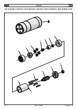
AM-0001

CODIGO

C.dad

DESCRIPCIÓN

1

71345183

1

Corona

2

71345382

1

Portasatelite extremo

3

71345181

4

Satelite

4

71345182

1

Satelite central

5

71345180

1

Empalme

6

71C00154

1

Cojinete 688ZZ

7

71345179

1

Platillo anterior

8

71345176

1

Cuerpo exterior

9

71345171

1

Perno

10

71345177

5

Aleta

11

71345173

1

Rotor

12

71345172

1

Platillo posterior

13

710943

1

Cojinete 624ZZ

A

713348

1

Motor completo

Summary of Contents for KJ45

Page 1: ...4 M12 MODE D EMPLOI PIECES DETACHEES PNEUMATISCH HYDRAULISCHES NIETWERKZEUG FÜR BLINDNIETMUTTERN M4 M12 BEDIENUNGSANLEITUNG ERSATZTEILE REMACHADORA OLEONEUMATICA PARA TUERCAS REMACHABLES M4 M12 INSTRUCCIONES DE USO PIEZAS DE REPUESTO NITOWNICA OLEO PNEUMATYCZNA DO NITONAKRĘTEK M4 M12 INSTRUKCJA OBSŁUGI CZĘŚCI ZAMIENNE МАСЛЯНО ПНЕВМАТИЧЕСКИЙ ЗАКЛЁПЫВАЮЩИЙ АППАРАТ ДЛЯ ВСТАВОК М4 М12 ИНСТРУКЦИИ ПО ИС...

Page 2: ...odifications et intégrations successives Die Unterzeichnete Fa Far S r l mit Sitz in Quarto Inferiore BO Via Giovanni XXIII Nr 2 ERKLÄRT hiermit auf ihre alleinige Verantwortung daß die Nietmaschine Typ KJ45 Pneumatisch hydraulisches Nietwerkzeug Anwendung für Blindnietmuttern M4 M12 auf das sich diese Erklärung bezieht den wesentlichen Sicherheitsanforderungen des DPR 459 96 für die Durchführungd...

Page 3: ...E D EMPLOI 20 BEDIENUNGSANLEITUNG 28 INSTRUCCIONES DE USO 36 INSTRUKCJA OBSŁUGI 44 ИНСТРУКЦИИ ПОA ИСПОЛЬЗОВАНИЮ 52 PARTI DI RICAMBIO 60 SPARE PARTS 62 PIECES DETACHEES 64 ERSATZTEILE 66 PIEZAS DE REPUESTO 68 CZĘŚCI ZAMIENNE 70 ДЕТАЛИ 72 KJ 45 KJ 45 I GB F E D PL RUS ...

Page 4: ... è valida se l attrezzo non viene utilizzato e non viene sottoposto a manutenzione nel modo specificato nel manuale di istruzione e manutenzione In caso di difetti o guasti la FAR S r l si impegna solamente a ripararee osostituire apropriadiscrezioneesclusiva icomponenti giudicati difettosi AVVERTENZE E MISURE Dl SICUREZZA indicate nel presente fascicolo In caso di perdite accidentali di olio che ...

Page 5: ...ndo la rivettatrice KJ45 assolutamente maneggevole Le possibilità di perdite dal sistema oleodinamico sono precluse dall impiego di guarnizioni a tenuta che eliminano questo problema Nome e indirizzo costruttore Modello DATI TECNICI Pressione di esercizio 6 7 BAR Diametro interno minimo tubo alimentazione aria compressa ø min 8 mm Consumo max aria libera per ciclo 11 NI Forza 6 BAR 28 KN Rumorosit...

Page 6: ...adeguato alla misura dell inserto che si vuole serrare in caso contrario procedere al cambio di formato pag 9 La coppia tirantefilettato A testina B montatasullarivettatriceinconfezione corrisponde ad una filettatura di M10 Primadiutilizzarelarivettatriceedopoognicambiodiformatooccorre regolare la corsa in funzione delle dimensioni del tipo di inserto e dello spessore del materiale da serrare Prim...

Page 7: ...a in battuta con la testina B verificando che il tirante A fuoriesca di 2mm dall inserto In caso di ulteriore regolazione del tirante A procedere come riportato a pag 10 È possibile ora procedere alla messa in posa dell inserto premendo il pulsante D e mantenendolo premuto fino al completo disimpegno del tirante fig f5 Per una corretta posa ed un corretto funzionamento della macchina è necessario ...

Page 8: ...arre l asta P dalla relativa sede f7 ed inserirla nel foro presente nella parte inferiore del pulsante di comando D esercitando una leggera pressione Una volta liberato il tirante dall inserto riporre nuovamente l asta nella relativa sede per non disperderla f9 f7 ATTENZIONE Eseguire questa operazione trattenendo saldamente la rivettatrice in modo da impedirle eventuali bruschi movimenti che potre...

Page 9: ...i di mm 20 per smontare la ghiera K da cui sarà estratto il tirante filettato A Nota Lo sbloccaggio della ghiera K deve necessariamente avvenire per mezzo di due chiavi come indicato in figura f12 l inosservanza di questa procedura può provocare danni alla rivettatrice Dopo avere sostituito il tirante filettato A con quello della misura desiderata rimontare la ghiera K e proseguire eseguendo in se...

Page 10: ...lunghezzadesideratasultirante filettato fino a che la testa dell inserto vada in battuta con la testina B della rivettatrice La testina è regolata correttamente se il tirante filettato fuoriesce per circa 2 mm dall inserto avvitato su di esso In casocontrariosbloccarelaghiera C medianteunachiavecommerciale di mm 22 quindi avvitare o svitare la testina B fino a trovare la giusta posizione al termin...

Page 11: ...in un apposito contenitore e avvalersi sucessivamente di una ditta autorizzata allo smaltimento dei rifiuti MANUTENZIONE Manutenzione giornaliera Controllare che il tirante filettato non sia danneggiato Controllare il sistema di alimentazione dell aria compressa Controllare che la corsa dell attrezzo sia adatta per inserire l inserto selezionato vedere le istruzioni relative alla regolazione della...

Page 12: ...y overhauled GUARANTEE AND TECHNICAL ASSISTANCE FAR riveting tools are covered by a 12 months guarantee The period of guarantee starts from the date of delivery specified on the invoice or delivery note The guarantee covers the user buyer when the tool is bought through an authorized dealer and only when it is employed for the uses it was conceived for The guarantee is not valid if the tool is not...

Page 13: ...ibilities of leakage from the oil dynamic system are eliminated by some sealed gaskets which solve this problem Name and address of manufacturer Model TECHNICAL DATA Working pressure 6 7 BAR Min int diam of the compressed air feeding hose ø min 8 mm Max free air consumption per cycle 11 NI Force 6 BAR 28 KN Noise level 75 db A Weight with equipment for M10 2 9 Kg Working temperature 5 50 Root mean...

Page 14: ...e of the insert to clamp otherwise change the size page17 The couple tie rod A head B assembled on this riveting tool corresponds to a M10 thread Before using the riveting tool and after each change of size the stroke shouldbeadjustedaccordingtothedimensions typeoftheinsertand thickness of the material to clamp Before carrying out this operation rotate the knob M according to the direction of the ...

Page 15: ...e rod Make sure that the insert head touches the head B checking that the tie rod A comes out of 2mm from the insert In case of further adjustments of the tie rod A follow the instructions of page 18 It is possible to place the insert pushing the button D and keeping it pushed up to the complete release of the tie rod fig f5 For a correct placing and right working of the machine the inserts to be ...

Page 16: ...he push rod P from its seat f7 and introduce it into the hole in the lower part of the tensile strength button D pushing it slightly When the tie rod is free from the insert put the rod back in its seat for not loosing it f9 f7 ATTENTION Carry out this operation keeping the rivetingtoolfirmlyinordertoavoidsharpmovements which could damage people or things f8 P D P P P f9 f8 ...

Page 17: ...andard spanners for disassem bling the ring nut K and extract the threaded tie rod A Note Usetwospannersforunblockingtheringnut K asindicated in figure f9 the inobservance of this procedure can damage the riveting tool After having replaced the threaded tie rod A with that one of the right size assembletheringnut K againandcarryouttheabove mentioned operationsinreverseorder beingsurethatthecompone...

Page 18: ...rew an insert of the desired length on the threaded tie rod manually until the insert head touches the riveting tool head B The head is adjusted correctly if the threaded tie rod comes out of the insert screwed on it of about 2 mm Otherwise unblock the ring nut C with a 22 mm standard spanner then screw or unscrew the head B up to the right position and block the ring nut C ATTENTION Disconnect th...

Page 19: ...u must put the oil in a suitable container and contact a company authorized to dispose of wastes MAINTENANCE Daily maintenance Check that the threaded tie rod is not damaged Check the supply system of the compressed air Check that the stroke of the tool is suitable for the selected insert to clamp see the pertaining instructions for adjusting the stroke indicated at page 14 Checkthatthereareneithe...

Page 20: ...ilisée pour l usage prévu La garantie n est pas applicablesilamachinen estpasutiliséenisoumiseauxinterventions d entretien prévues dans le manuel d utilisation et d entretien En cas de défaut ou autre anomalie FAR S r l s engage uniquement à réparer ou changer selon son choix les pièces défectueuses INSTRUCTIONS ET MESURES DE SECURITE En cas de fuites imprévues de huile au contact de la peau il fa...

Page 21: ...ues de fuites du système oléodynamique sont éliminés par l utilisation de joints à haute résistance Nom et adresse du constructeur Modèle CARACTERISTIQUES TECHNIQUES Pression de service 6 7 BARS Diamètre interne minimum tuyau d alimentation air comprimé ø min 8 mm Consommation air max par cycle 11 NI Force 6 BARS 28 KN Bruit 75 db A Poids avec équipement pour M10 2 9 kg Température d utilisation 5...

Page 22: ...aille de l insert à sertir si tel n est pas le cas procéder auchangementdeformat page25 Lecoupletirantfileté A tête B monté sur la riveteuse correspondant à un filetage de M10 Avant d utiliser la riveteuse et après chaque changement de format il estnécessairederéglerlacourseenfonctiondesdimensions duformat de l insert et de l épaisseur du matériau à sertir Avant de procéder à cette opération tourn...

Page 23: ...utéecontrelatête B en s assurant que le tirant A dépasse de l insert de 2 mm En cas de nouveau réglage du tirant A procéder comme indiqué page 26 Il est à présent possible de procéder à la pose de l insert en appuyant sur le bouton D et en le maintenant enfoncé jusqu à ce que le tirant fig f5 soit libéré Pour assurer correctement la pose et donc le bon fonctionnement de la machine il est nécessair...

Page 24: ... f7 et l introduire dans le trou présent sur la partie inférieure du bouton de traction D en exerçant une légère pression Une fois le tirant libéré de l insert replacer la tige dans son logement pour ne pas risquer de l égarer f9 f7 ATTENTION Effectuer cette opération en tenant fermement la riveteuse de façon à éviter les mouvements brusques susceptibles de provoquer des dommages physiques et maté...

Page 25: ...deux clés commerciales de 20 mm pour démonter la bague K d où le tirant fileté A doit être extrait Note ledéblocagedelabague K doitnécessairements effectuer àl aidededeuxcléscommeindiquésurlafigure f9 lenon respect de cette procédure peut causer des dommages à la riveteuse Après avoir remplacé le tirant fileté A par le tirant de la dimension voulue remonterlabague K eteffectuerlesopérationsprécéde...

Page 26: ...ongueur voulue sur le tirant fileté jusqu à ce que la tête de l insert soit en butée contre la tête B de la riveteuse Latêteestcorrectementrégléesiletirantdépassed environ 2 mm l insert vissé sur celui ci Si tel n est pas le cas débloquer la bague C à l aide d une clé commerciale de 22 mm puis visser ou dévisser la tête B jusqu à ce que soit obtenue la bonne position ensuite bloquer la bague C ATT...

Page 27: ...rcuit hydraulique récupérer l huile dans un récipient et la remettre à un centre agréé de collecte des déchets ENTRETIEN Entretien quotidien s assurer que le tirant fileté n est pas endommagé contrôler le système d alimentation d air comprimé s assurer que la course de l outil est adapté à la pose de l insert sélectionné voir les instructions relatives au réglage de la course page 22 s assurer de ...

Page 28: ...einen autorisierten Händler gekauft wird sowie nur dann wenn es für die vorgesehenen Verwendungszwecke eingesetzt wird Die Garantie ist nicht gültig wenn das Werkzeug nicht in der im Bedienungs und Wartungsanleitung spezifizierten Weise gewartet und bedient wird Bei Mängeln oder Fehlern ist die FAR S r l nur verpflichtet die für fehlerhaft befundenen Komponenten nach ausschließlich eigenem Ermesse...

Page 29: ...chen das Nietwerkzeug KJ45 absolut handlich Die Möglichkeiten einer Undichtheit von Öl aus dem öldynamischen SystemwerdendurchdieVerwendungvonundurchlässigenDichtungen verhindert die dieses Problem eliminieren Name und Adresse der Herstellfirma Modell TECHNISCHE DATEN Betriebsdruck 6 7 BAR Mindestinnendurchmesser Druckluftschlauch ø min 8 mm Max Luftverbrauch pro Takt 11 NI Setzkraft bei 6 BAR 28 ...

Page 30: ...ist FührenSieandernfallsdenDimensionswechsel durch Seite 33 Das auf der Nietmaschine schon montierte Paar Gewindedorn A Mundstück B entspricht einem M10 Gewinde VorderVerwendungderNietmaschineundnachjedemDimensionswechsel istderHubgemäßAbmessungen TypvonBlindnietmutterundStärkedeszu befestigendenMaterialseinzustellen DrehenSiezuerstdenKnopf M gemäß der Pfeilrichtung zur Erhöhung des Hubs und zur V...

Page 31: ...utterbisAnschlag mit dem Mundstück B liegt indem Sie prüfen ob der Gewindedorn A um 2 mm aus der Blindnietmutter hervorsteht Bei einer weiteren Einstellung des Gewindedornes A gehen Sie wie auf Seite 34 wiedergegeben vor SiekönnenjetztdieBlindnietmuttersetzen indemSiedenBedienungsknopf D bis zur vollkommenen Freigabe des Gewindedornes drücken und gedrückt halten fig f5 Für einen korrekten Setzvorg...

Page 32: ...und fügen ihn in das Loch im unteren Teil des Bedienungsknopfes D ein indem Sie einen leichten Druck ausüben Nachdem Sie den Gewindedorn von der Blindnietmutter gelöst haben setzen Sie den Dorn wieder in seinen Sitz damit dieser nicht verloren geht f9 f7 ACHTUNG FührenSiediesenVorgangaus indemSie dieNietmaschineganzfesthalten sodassmögliche ruckartige Bewegungen vermieden werden die Personen oder ...

Page 33: ... ab Montieren Sie mit zwei handelsüblichen 20mm Schlüsseln den Ring K ab aus dem der Gewindedorn A herausgezogen wird Hinweis DieLösungdesRings K istunbedingtmitzweiSchlüsselnwie inderAbbildung f9 bezeichnetauszuführen DieNichtbeachtungdieses Verfahrens kann Schäden an der Nietmaschine herbeiführen NachderAuswechselungdesGewindedornes A durchdenDornmitdem gewünschten Maß montieren Sie den Ring K w...

Page 34: ... auf den Gewindedorn bis der Blindnietmutterkopf bis Anschlag mit dem Mundstück B derNietmaschineliegt DasMundstückistkorrekteingestellt wennderGewindedornumzirka2mmausderaufdiesemverschraubten Blindnietmutterhervorsteht LösenSieandernfallsdieMundstücknutmutter C mittels eines handelsüblichen 22mm Schlüssels und schrauben Sie das Mundstück B zu oder auf bis die richtige Position gefunden ist und s...

Page 35: ... bei einer vollständigen Entleerung des öldynamischen Kreises das gesamte Öl in einem besonderen Behälter auf und wenden Sie anschließend zur Entsorgung an eine Fachfirma WARTUNG Tägliche Wartung Prüfen Sie dass der Gewindedorn nicht beschädigt ist Prüfen Sie das Druckluftversorgungssystem Prüfen Sie dass der Werkzeugshub zur Befestigung der gewählten Blindnietmuttergeeignetist siehedieentsprechen...

Page 36: ...ra los cuales ha sido creado La garantía no es válida si el utensilio no es empleado o es sometido a manutención en la manera indicada en el manual de instrucción y manutención EncasodedefectosoaveríaslaFARS r l seempeñasóloenreparary o sustituir los componentes que ella misma considera defectuosos ADVERTENCIASY MEDIDAS DE SALVAGUARDIA fluidos según las características indicadas en eso fascículo E...

Page 37: ...lviendo la remachadora KJ45 absolutamente maniobrable Las posibilidades de perdida por el sistema oleodinámico son eliminadas con el uso de juntas que eliminan este problema Nombre y dirección del productor Modelo DATOS TÉCNICOS Presión de trabajo 6 7 BAR Diámetro interno mínimo tubo alimentación aire comprimido ø min 8 mm Consumo máx aire libre por ciclo 11 NI Fuerza 6 BAR 28 KN Ruido 75 db A Pes...

Page 38: ... la remachadora sea apropiada a la medida de la tuerca que se quiere apretar en caso contrario efectuar el cambio de formato pág 41 La pareja tirante fileteado A cabeza B ensambladasobreestaremachadora corresponde a un fileteado de M10 Antes de emplear la remachadora y después de cada cambio de formato hay que regular la carrera según las dimensiones el formato de la tuerca y el espesor del materi...

Page 39: ...camente sobre el tirante fileteado Asegurarse que la cabeza de la tuerca toque la cabeza B averiguando que el tirante A salga de 2mm de la tuerca En caso de regulación adicional del tirante A actuar como indicado en pág 42 Es posible colocar la tuerca apretando el pulsador D y manteniéndolo apretado hasta la completa liberación del tirante fig f5 Paraunacorrectacolocaciónyuncorrectofuncionamientod...

Page 40: ...manera siguiente Quitar la varilla P de su sede f7 e introducirla en el agujero presente en la parte inferior del pulsador de tracción y presionar ligeramente G Después de haber liberado el tirante de la tuerca volver a poner la varilla en su sede para no perderla f9 f7 ATENCIÓN Efectuar esta operación teniendo firmementelaremachadorademaneraqueposibles movimientos bruscos no puedan dañar a person...

Page 41: ...r la virola K de la cual será quitado el tirante fileteado A Nota El desbloqueo de la virola K tiene que ocurrir por medio de las llaves como indicado en figura f9 la falta de respecto de este procedimiento puede causar daños a la remachadora Después de haber sustituido el tirante fileteado A con aquél de la medida deseada volver a montar la virola K y continuar ejecutando las operaciones susodich...

Page 42: ...ledelalongitudqueridasobreeltirante fileteadomanualmentehastaquelacabezadelatuercatoquelacabeza B delaremachadora Lacabezaesajustadacorrectamentesieltirante fileteadosaledelatuercaatornilladosobresímismoaproximadamente de 2 mm En caso contrario desbloquear la virola C con una llave estándar de mm 22 pues atornillar o destornillar la cabeza B hasta encontrar la justa posición al final bloquear la v...

Page 43: ...n una firma autorizada para la eliminación de desechos MANUTENCIÓN Manutención diaria Controlar que el tirante fileteado no se encuentre estropeado Controlar el sistema de alimentación del aire comprimido Controlar que la carrera del utensilio sea apropiada para introducir la tuerca remachable elegida véase las instrucciones relativas al ajuste de la carrera indicadas en la página 38 Controlar que...

Page 44: ...ięczną gwarancją która biegnie od daty zakupu Rozpatrzenie gwarancji należy do autoryzowanego sprzedawcy FAR Gwarancji nie podlegają uszkodzenia powstałe wskutek użycia narzędzia niezgodnego z zaleceniami niniejszej instrukcji W przypadku stwierdzenia wady fabrycznej produktu Þrma FAR zobowiązuje się do jego naprawienia lub wymiany na nowy BEZPIECZNA PRACA Z NARZĘDZIEM Narzędzie może być przenoszo...

Page 45: ...goergonomię Ponadto udoskonalony system uszczelniaczy eliminuje możliwość spadku mocy zacisku Dane producenta Model DANE TECHNICZNE Ciśnienie robocze 6 7 BAR Minimalna średnica wewn przewodu zasilania ø min 8 mm Maksymalne zużycie powietrza w cyklu 11 NI Siła 6 BAR 28 KN Hałas 75 db A Waga z trzpieniem M10 2 9 Kg Temperatura otoczenia 5 50 Częstotliwość przyspieszenia Ac 2 5 m sec2 Ø 50 Ø 130 296 ...

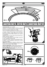
Page 46: ...rzygotowania powietrza F WSTĘPNE CZYNNOŚCI PRZED URUCHOMIENIEM rys f2 f3 Sprawdzamy czy trzpień gwintowany A i głowica B które są na nitownicy mają żądaną średnicę Jeżeli tak nie jest wymieniamy je na żądaną średnicę Fabrycznie montuje się na nitownicy trzpień i głowicę M10 Po każdej wymianie trzpienia na inną średnicę upewniamy się że regulacja siły zacisku jest prawidłowa Obracając pokrętło M w ...

Page 47: ...e rys f4 Upewniamy się że kołnierz nitonakrętki styka się z krawędzią głowicy B i że trzpień wystaje z nitonakrętki na ok 2 mm A W tym momencie możemy przystąpić do montażu nitonakrętki w wywierconymotworzezapomocąprzycisku D któryprzezchwilę przytrzymujemydomomentuzaciśnięcianitonakrętkiiwykręcenia trzpienia nitownicy z nitonakrętki rys f5 Aby nitonakrętki prawidłowo mocowały się w otworach muszą...

Page 48: ...rętki należy f7 wyjąć szpilkę P z gniazda f7 następnie wsuwamy ją w otwór u dołu przycisku D lekko naciskając Po wykręceniu trzpienia szpilkę P wsuwamy z powrotem do gniazda f9 f7 UWAGA Powyższą czynność wykonujemy mocno trzymając nitownicę w przeciwnym razie jej gwałtowne poruszenie może doprowadzić do uszkodzenia lub zagrażać użytkownikowi f8 P D P P P f9 f8 ...

Page 49: ... mm odkręcamy przewód głowicy O następnie używając 2 kluczy 20 mm wykręcamy pierścień K i wyjmujemy gwintowany trzpień A Uwaga odkręcenie pierścienia K należy koniecznie wykonać za pomocą 2 kluczy 20 mm jak na rys f12 w innym przypadku można uszkodzić nitownicę Pozałożeniunowegotrzpienia A nakręcamypierścień K ipowtarzamy w odwrotnej kolejności wcześniejsze czynności należy się przy tym upewnić że...

Page 50: ...cznie nakręcamy nitonakrętkę na gwintowany trzpień tak aby kołnierz nitonakrętki dotykał krawędzi głowicy B Pozycja głowicy jest prawidłowa jeżeli trzpień wychodzi z nitonakrętki na ok 2 mm W przeciwnym razie poluzować pierścień C kluczem 22 mm następnie obrócić głowicę tak aby trzpień wychodził z nitonakrętki na 2 mm Następnie blokujemy głowicę B pierścieniem blokującym C Uwaga Powyższe czynności...

Page 51: ... do odpowiedniego pojemnika a następnie skorzystać z usług Þrmy upoważnionej do usuwania odpadów KONSERWACJA Konserwacja codzienna sprawdzamy czy gwintowany trzpień nie jest uszkodzony sprawdzamy instalację zasilania powietrzem sprawdzamy czy siła zacisku jest odpowiednio ustawiona do danej nitonakrętki s 46 upewnić się że nie ma wycieków oleju lub nieszczelnych przewodów powietrza upewnić się ze ...

Page 52: ...пользуется и не подвергается техническому обслуживанию в строгом соответствии с инструкциями в руководстве по эксплуатации и техническому обслуживанию При наличии брака или повреждений Far S r l берет на себя обязательствопочинитьи илизаменитьтолькотедетали которые по собственному усмотрению Компания будет считать бракованными РЕКОМЕНДАЦИИ И МЕРЫ БЕЗОПАСНОСТИ инструментом указанным в главе Техниче...

Page 53: ... в обращении инструментом Вероятность утечек гидродинамической системы с масляной средой сведена к нулю благодаря использованию герметических уплотнений которые полностью решают данную проблему Наименование и адрес фирмы изготовителя Модель ТЕХНИЧЕСКИЕ ДАННЫЕ Рабочее давление 6 7 бар Минимальный внутренний диаметр шланга подачи сжатого воздуха ø миним 8 мм Максимальное потребление свободного возду...

Page 54: ...обходимо произвести смену формата стр 57 Набор распорка с резьбой А головка В смонтированные на заклёпывающем аппарате на предприятии изготовителе соответствуют резьбе М10 Перед использованием заклёпывающего аппарата и после каждой смены форматанеобходимоотрегулироватьходвсоответствиисразмерами типом вставкиитолщинойзажимаемогоматериала Передтем какосуществлять этуоперацию необходимоповернутьрукоя...

Page 55: ...а вставки соприкасается с головкой В и проверить выступает ли распорка из вставки на 2 мм Припроведениидополнительнойрегулировкираспоркиследоватьпорядку действий описанному на странице 58 Теперь можно установить вставку нажав на кнопку D и не отпускать её до полного освобождения распорки рис f5 Для правильной установки и корректного функционирования аппарата необходимо чтобы устанавливаемые вставк...

Page 56: ...6 Вынуть штырь Р из соответствующего гнезда f7 и вставить его в отверстие расположенное в нижней части кнопки управления D слегка нажимая на него Как только распорка будет освобождена необходимо поместить штырь на место чтобы его не потерять f9 f7 ВНИМАНИЕ Производить данные действия крепко держа заклёпывающий аппарат чтобы предотвратить резкие движения которые могут нанести ущерб людям или оборуд...

Page 57: ...я головки О При помощи двух стандартных ключей 20 мм разобрать блокирующее кольцо К и вынуть резьбовую распорку А Примечание разблокирование зажимного кольца К должно обязательно выполняться с помощью двух ключей как показано на рисунке f9 несоблюдение данного условия может стать причиной повреждения заклёпывающего аппарата После замены резьбовой распорки А на распорку требуемого размера необходим...

Page 58: ...вую распорку до тех пор пока головка вставки не будет соприкасаться с головкой В заклёпывающего аппарата Головка отрегулирована правильно если распорка выступает примерно на 2 мм из накрученной на неё вставки В противном случае необходимо разблокировать зажимное кольцо С при помощи стандартного ключа 22 мм а затем отвинтить или завинтить головку В пока не будет достигнуто требуемое положение В кон...

Page 59: ...ать всёмаславспециальнуюёмкостьипередатьвспециальныйпунктпосбору и переработке промышленных отходов ТЕХНИЧЕСКОЕ ОБСЛУЖИВАНИЕ Повседневное обслуживание Проверить целостность резьбовой тяговой штанге Проверить систему подачи сжатого воздуха Проверитьподходитлиходаппаратадляустановкивыбраннойвставки смотрите инструкции по регулировке хода на странице 54 Проверить имеются ли утечки воздуха или масла П...

Page 60: ...7 66 N674 70 82 71C00522 1 Guarnizione OR 5 615 PARKER N674 70 83 710914 1 Guarnizione OR 2 116 PARKER N552 90 100 71C00297 2 Guarnizione OR 6 700 PARKER N674 70 101 713398 1 Guarnizione OR 2 340 PARKER N674 70 102 710350 1 Guarnizione OR 2 109 PARKER N674 70 105 713192 5 Gabbia KITB 74000027 1 Kit contenitore tirante KITQ 74000037 1 Kit oleodinamico 26 711722 1 Guarnizione BALSELE B 094063 B NEI ...

Page 61: ...1 Guarnizione BALSELE B 075047 82 71C00522 1 Guarnizione OR 5 615 PARKER N674 70 83 710914 1 Guarnizione OR 2 116 PARKER N552 90 84 713319 1 Dado M22 X 1 25 85 713320 1 Raccordo 86 713315 1 Stelo 87 713197 1 Coperchio 88 713194 1 Pomello 89 713316 1 Ghiera 90 713191 1 Disco 91 712575 1 Vite TSEI M5X12 UNI 5933 92 713404 4 Vite TSP autof ø2 5x12 per plastica 93 713317 1 Raccordo flangiato 94 713318...

Page 62: ...2 1 Gasket OR 5 615 PARKER N674 70 83 710914 1 Gasket OR 2 116 PARKER N552 90 100 71C00297 2 Gasket OR 6 700 PARKER N674 70 101 713398 1 Gasket OR 2 340 PARKER N674 70 102 710350 1 Gasket OR 2 109 PARKER N674 70 105 713192 5 Casing KITB 74000027 1 Tie rod container kit KITQ 74000037 1 Oil dynamic kit 26 711722 1 Gasket BALSELE B 094063 B NEI 34 713389 1 Gasket BALSELE B 157118 B NEI 80 711827 1 Ga...

Page 63: ... B 075047 82 71C00522 1 Gasket OR 5 615 PARKER N674 70 83 710914 1 Gasket OR 2 116 PARKER N552 90 84 713319 1 Nut M22 X 1 25 85 713320 1 Connector 86 713315 1 Stem 87 713197 1 Cover 88 713194 1 Knob 89 713316 1 Ring nut 90 713191 1 Disc 91 712575 1 Screw TSEI M5X12 UNI 5933 92 713404 4 Tapping screw TSP ø2 5x12 for plastic 93 713317 1 Flanged connector 94 713318 1 Driving shaft 95 713321 1 Double ...

Page 64: ...arniture OR 5 615 PARKER N674 70 83 710914 1 Garniture OR 2 116 PARKER N552 90 100 71C00297 2 Garniture OR 6 700 PARKER N674 70 101 713398 1 Garniture OR 2 340 PARKER N674 70 102 710350 1 Garniture OR 2 109 PARKER N674 70 105 713192 5 Cage KITB 74000027 1 Kit conteneur Tirant KITQ 74000037 1 Kit hydraulique 26 711722 1 Garniture BALSELE B 094063 B NEI 34 713389 1 Garniture BALSELE B 157118 B NEI 8...

Page 65: ...LSELE B 075047 82 71C00522 1 Garniture OR 5 615 PARKER N674 70 83 710914 1 Garniture OR 2 116 PARKER N552 90 84 713319 1 Ecrou M22 X 1 25 85 713320 1 Raccord 86 713315 1 Tige 87 713197 1 Couvercle 88 713194 1 Bouton 89 713316 1 Embout 90 713191 1 Disque 91 712575 1 Vis TSEI M5X12 UNI 5933 92 713404 4 Vis autotaraudeuse TSP ø2 5x12 pour plastique 93 713317 1 Raccord à bride 94 713318 1 Arbre d entr...

Page 66: ... 66 N674 70 82 71C00522 1 Dichtung OR 5 615 PARKER N674 70 83 710914 1 Dichtung OR 2 116 PARKER N552 90 100 71C00297 2 Dichtung OR 6 700 PARKER N674 70 101 713398 1 Dichtung OR 2 340 PARKER N674 70 102 710350 1 Dichtung OR 2 109 PARKER N674 70 105 713192 5 Käfig KITB 74000027 1 Gewindedorn Behälter Kit KITQ 74000037 1 Öldynamisches Kit 26 711722 1 Dichtung BALSELE B 094063 B NEI 34 713389 1 Dichtu...

Page 67: ...75047 82 71C00522 1 Dichtung OR 5 615 PARKER N674 70 83 710914 1 Dichtung OR 2 116 PARKER N552 90 84 713319 1 Mutter M22 X 1 25 85 713320 1 Anschlusstück 86 713315 1 Schaft 87 713197 1 Dekel 88 713194 1 Knopf 89 713316 1 Nutmutter 90 713191 1 Scheibe 91 712575 1 Schraube TSEI M5X12 UNI 5933 92 713404 4 Schneidschraube TSP ø2 5x12 für Kunststoff 93 713317 1 Flanschanschlußstück 94 713318 1 Mitnehme...

Page 68: ... 70 78 71C00356 2 Junto OR 1 78x7 66 N674 70 82 71C00522 1 Junto OR 5 615 PARKER N674 70 83 710914 1 Junto OR 2 116 PARKER N552 90 100 71C00297 2 Junto OR 6 700 PARKER N674 70 101 713398 1 Junto OR 2 340 PARKER N674 70 102 710350 1 Junto OR 2 109 PARKER N674 70 105 713192 5 Jaula KITB 74000027 1 Kit contenedor tirante KITQ 74000037 1 Kit oleodinamico 26 711722 1 Junto BALSELE B 094063 B NEI 34 713...

Page 69: ... 71C00522 1 Junto OR 5 615 PARKER N674 70 83 710914 1 Junto OR 2 116 PARKER N552 90 84 713319 1 Tuerca M22 x 1 25 85 713320 1 Empalme 86 713315 1 Vastago 87 713197 1 Tapon 88 713194 1 Perilla 89 713316 1 Virola 90 713191 1 Disco 91 712575 1 Tornillo TSEI M5x12 UNI 5933 92 713404 4 Tornillo TSP autorroscante Diam 2 5x12 por plastico 93 713317 1 Empalme rebordeado 94 713318 1 Arbol de arrastre 95 71...

Page 70: ...522 1 Gasket OR 5 615 PARKER N674 70 83 710914 1 Gasket OR 2 116 PARKER N552 90 100 71C00297 2 Gasket OR 6 700 PARKER N674 70 101 713398 1 Gasket OR 2 340 PARKER N674 70 102 710350 1 Gasket OR 2 109 PARKER N674 70 105 713192 5 Casing KITB 74000027 1 Zestaw pojemników na trzpienie KITQ 74000037 1 Oil dynamic kit 26 711722 1 Gasket BALSELE B 094063 B NEI 34 713389 1 Gasket BALSELE B 157118 B NEI 80 ...

Page 71: ...0 83 710914 1 Uszczelka OR 2 116 P N 552 90 84 713319 1 Nakrętka M22x1 25 85 713320 1 Przyłącze 86 713315 1 Tłok 87 713197 1 Pokrywa korpusu 88 713194 1 Pokrętło 89 713316 1 Pierścień 90 713191 1 Tarcza pokrętła 91 712575 1 Śruba VSPM5X12 UNI5933 92 713404 4 Śruba samogwint D 2 5X12 93 713317 1 Złącze kołnierzowe 94 713318 1 Wał 95 713321 1 Śruby 96 713322 1 Śruba M5 97 713199 1 Sprężyna przycisku...

Page 72: ...3 N674 70 78 71C00356 2 Уплотнительное кольцо OR 1 78x7 66 N674 70 82 71C00522 1 Уплотнительное кольцо OR 5 615 PARKER N674 70 83 710914 1 Уплотнительное кольцо OR 2 116 PARKER N674 70 100 71C00297 2 Уплотнительное кольцо OR 6 700 PARKER N674 70 101 713398 1 Уплотнительное кольцо OR 2 340 PARKER N674 70 102 710350 1 Уплотнительное кольцо OR 2 109 PARKER N674 70 105 713192 5 Кожух KITB 74000027 1 K...

Page 73: ...отнительноекольцоOR2 010PARKER N674 70 A H I 71 72C00003 1 Корпус 72 713403 1 Шар ø 5 5 73 71345272 1 Крышка клапана 74 71345273 1 Катушка 75 713400 7 Уплотнительное кольцо OR 5 616 PARKER N674 70 76 72A00028 1 Воздушный фитинг 77 71C00355 2 Уплотнительное кольцо OR 1 78x8 73 N674 70 78 71C00356 2 Уплотнительное кольцо OR 1 78x7 66 N674 70 79 713304 1 Фитинг направляющего стержня 80 711827 1 Уплот...

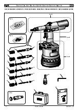
Page 74: ...ICAMBIO SPARE PARTS PIECES DETACHEES ERSATZTEILE PIEZAS DE REPUESTO CZĘŚCI ZAMIENNE ДЕТАЛИ 1 25 4 7 10 14 18 5 9 12 16 20 19 15 11 8 6 3 21 24 17 13 Tav 02 KIT A KIT B Tav 03 Tav 04 22 23 KIT Q 2 Tav 1 4 Tab 1 4 Tab 1 4 Taf 1 4 Tab 1 4 Tab 1 4 Черт 1 4 ...

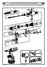
Page 75: ... DETACHEES ERSATZTEILE PIEZAS DE REPUESTO CZĘŚCI ZAMIENNE ДЕТАЛИ 49 52 39 35 34 37 59 28 30 27 54 40 58 53 53 48 26 29 36 38 32 31 KIT F KIT D KIT C KIT E 57 56 55 46 47 45 44 43 42 41 KIT D 51 50 KIT C KIT F KIT E 33 60 Tav 2 4 Tab 2 4 Tab 2 4 Taf 2 4 Tab 2 4 Tab 2 4 Черт 2 4 ...

Page 76: ...I DI RICAMBIO SPARE PARTS PIECES DETACHEES ERSATZTEILE PIEZAS DE REPUESTO CZĘŚCI ZAMIENNE ДЕТАЛИ 65 61 62 63 64 70 KIT H KIT M KIT I 66 KIT H 67 KIT I KIT L 68 KIT A 69 70 68 KIT A 69 KIT M Tav 3 4 Tab 3 4 Tab 3 4 Taf 3 4 Tab 3 4 Tab 3 4 Черт 3 4 ...

Page 77: ...ETACHEES ERSATZTEILE PIEZAS DE REPUESTO CZĘŚCI ZAMIENNE ДЕТАЛИ KIT N KIT P 86 82 80 81 83 79 75 75 105 70 89 91 90 71 76 103 104 77 78 77 78 99 99 100 102 84 100 96 101 73 74 93 95 94 97 72 88 92 87 98 85 KIT O KIT N KIT P Tav 4 4 Tab 4 4 Tab 4 4 Taf 4 4 Tab 4 4 Tab 4 4 Черт 4 4 ...

Page 78: ...78 KJ 45 KJ 45 Date 10 2008 Revision 04 PARTI DI RICAMBIO SPARE PARTS PIECES DETACHEES ERSATZTEILE PIEZAS DE REPUESTO CZĘŚCI ZAMIENNE ДЕТАЛИ 10 11 12 13 2 3 1 4 5 6 7 8 9 AM 0001 ...

Page 79: ......

Page 80: ...STEMAS DE FIJACION SYSTEMY MOCOWANIA СИСТЕМЫ КРЕПЛЕНИЯ SEDE HEAD OFFICE SIEGE HAUPTSITZ SEDE SIEDZIBA ОФИСНЫЙ ЦЕНТР Via Giovanni XXIII 2 40057 Quarto Inferiore Bologna Italy Tel 39 051 6009511 TELEFAX 39 051 767443 DEPOSITO WAREHOUSE DEPOT WARENLAGER ALMACEN ODDZIAŁ СКЛАД Via Archimede 8 20099 Sesto San Giovanni Milano Italy Tel 39 02 2409634 TELEFAX 39 02 26222279 ...

Reviews: