13400 Owner’s Manual
P/N 446613 Issue I Rev. A
III-1
Section III : Installation and Wiring
Parts Supplied
446688 or 446689 Backbox Assembly (red or black)
413537 or 413538 Door Assembly (red or black)
413535 or 413536 Transformer Assembly (120VAC or 240VAC)
413540 Sub-Chassis Assembly
412387 Ground Wire Assembly
18965 #6-32 Keps Nuts (2)
942665 3.9K Ohm 1/2W Resistor (4)
29529-11 #6-32 x 1/4” Screws (10)
942633 1.8K Ohm 1W Resistor (4)
446613 Owner’s Manual
942685 2.2K Ohm 1/2W Resistor (4)
446691 Operating Instructions
942667 24K Ohm 1/2W Resistor (2)
443269 Screwdriver
Installation
Installation is to be done only by qualified personnel who have thoroughly read and
understood these instructions.
Cautions:
1. It is recommended that the Sub-Chassis assembly be removed for any procedure
that may cause dust, metal shavings, grease or any such matter that may affect the
circuit boards and/or parts.
2. There may be several sources of power into the control unit. Each source must be
disconnected prior to installing or removing modules, connecting or disconnecting
wiring, and programming jumpers.
Panel Location
The control unit should be located near an exit at ground level, where the normal
ambient temperature is maintained within the control unit specification. (See General
Specifications in Section I). The unit should be in an area that is free of dust, vibration,
moisture and condensation.
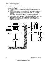
Mount the Enclosure
Follow the appropriate instructions for surface or semi-flush mounting.
firealarmresources.com


