Section III. Installation and Wiring
III-4
P/N 446613 Issue I Rev. A
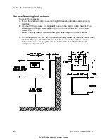
Knock out Knock-outs
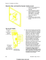
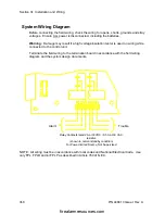
A. Prepare the enclosure for electrical wiring, break out the appropriate conduit entry
points. Note the wiring diagram requirements for nonpower-limited and power-
limited wiring separation.
B. Attach conduit (if required) and run wires as required. Label each field cable for
future reference.
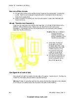
Attach Transformer Assembly
There are two versions of the transformer assembly: a 120VAC (P/N 413535) and a
240VAC (P/N 413536) version. Make sure you have the correct one for your
installation. (This stage must be accomplished before mounting the Sub-Chassis
Assembly into the enclosure.)
Caution: Remove cardboard
ring from around
transfomer terminals
before installation of the
transformer assembly.
A. Attach the Transfomer
Assembly to the Sub-
Chasisis Assembly using
two #6-32 keps nuts (P/N
18965) to secure. The
Transformer Assembly
electrical connections
should be facing down.
B. Connect the plug from the
Transformer Assembly to
the J7 connector on the
Main PCB assembly.
Configure the Control Unit
Set jumpers to match the desired functionality of the panel. See Section IV, “Setting Up
13400” for information about switch and jumper settings.
Warning: Failure to setup the switches may cause the improper detection and indication
of a fire event, as well as cause the improper evacuation of the building.
firealarmresources.com

