Section III. Installation and Wiring
III-6
P/N 446613 Issue I Rev. A
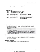
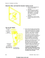
Mount the Door and Install the Operator Interface board
A. Place the Door Assembly onto
hinges of the Backbox
Assembly.
B. Secure the Operator Interface
board to the Door Assembly
using four #6-32 x 1/4” screws
(P/N 29529-11). The rubber
push buttons should face the
interior of the Backbox
Assembly.
C. Ensure that the LED’s are lined
up with the openings in the front
overlay..
Connect AC Supply
A. Wire up the AC supply to terminal block
TB2 on the main termination board. The
supply should originate from a separate,
fused circuit. It should be provided with
a breaker or other means of isolation.
Observe the wiring order -- the right
hand terminal is ground and must be
wired back to the electrical panel ground
(earth) bonding point or another good
ground acceptable to the authority
having jurisdiction and the electrical
inspector. The neutral wire must be
taken back to the electrical panel neutral
distribution bar and must not be
grounded. When wiring a two phase
240V system (with the appropriate
transformer fitted in the panel) the order
in which the phases are connected to
the top two terminals is not important.
/!\ Dangerous voltages will be
present on this terminal block and on
other components surrounding it and
the transformer when the AC supply
is turned on. Do not touch.
120VAC 50/60 Hz
1A Max.
or
240VAC 50/60 Hz.
0.5A Max.
Supervised
Non-power Limited
24V Battery Set
7 to 17.2 AH
Supervised
Non-Power Limited
Input Current 6A max.
Charge Voltage 28V max.
Charge Current 1A max.
Note: Branch-Circuit
must be protected by a
15A overcurrent device
firealarmresources.com


