13400 Owner’s Manual
P/N 446613 Issue I Rev. A
III-7
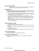
Apply Power to System
Apply AC power to the system. The AC Power On LED, System Trouble LED,
all IDC Trouble LEDs, and the trouble buzzer should be on.
Install Batteries
Warning: Improper battery connections or shorting battery terminals may damage the
panel and/or batteries and may cause personal injuries.
A. Place the batteries in the space provided in the bottom of the backbox. If larger than
12 AH battery set is required, a separate enclosure must be used. The 14050 may
be used for battery sets 17.2 AH and smaller.
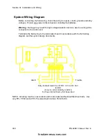
B. The panel uses a 24V battery set. Connect the two 12V batteries (or four 6V
batteries) in series with #12 AWG wire. Route the battery leads to the right of the
panel and up to the battery termination block, TB3. The battery leads are not power
limited.
C. Observe polarity. Connect the “B-” terminal from the panel into the black or “-”
terminal of the battery set and the “B+” terminal from the panel into the red or “+”
terminal of the battery set.
Check Supervised Circuits
To check the supervised circuits of the control unit:
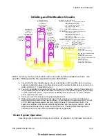
A. Place a 3.9K ohm resistor (color coded: orange, white, red) across each set of IDC
terminals.
B. Place a 24 K ohm resistor (color coded: red, yellow, orange) across each set of NAC
terminals.
C. Push System Reset button.
D. The System Trouble LED, all IDC Trouble LEDs, and the trouble buzzer should be
off.
Install Optional Modules
Follow the installation instructions provided in Appendix C.
Check Control Unit Operation
Check for proper operation of the panel functions. See Section II for “Operation
Instructions”.
firealarmresources.com


