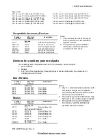
Section III. Installation and Wiring
III-8
P/N 446613 Issue I Rev. A
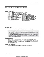
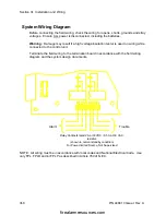
System Wiring Diagram
Before connecting the field wiring, check the wiring for opens, shorts, grounds and stray
voltages. Ensure ALL power is disconnected, including the batteries.
Warning: Damage may result if a high voltage insulation tester is used on wiring while
connected to the control unit.
Terminate the field wiring to the termination board in accordance with the field wiring
diagram and the system design documents.
NOTE: All wiring must be in accordance with local codes and National Electrical Code. Use
only FPL, FPLR and/or FPLP as described in Article 760 of N.E.C.
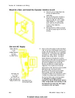
Alarm
Trouble
Relay Contacts rated 2A at 30VDC / 0.5 A at 30 VAC,
resistive
(shown in normal standby condition)
For Power-limited Source, Not Supervised
firealarmresources.com


