13400 Owner’s Manual
P/N 446613 Issue I Rev. A
III-9
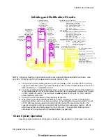
Initiating and Notification Circuits
NOTE: All wiring must be in accordance with local codes and National Electrical Code. Use
only FPL, FPLR and/or FPLP as described in Article 760 of N.E.C.
A. Connect the first four initiating device circuits to terminals on TB1 and TB6. Each circuit may
support an unlimited number of contact devices and the number of other devices shown in the
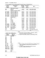
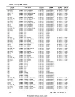
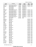
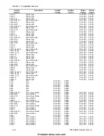
tables in Section V: Compatible Devices.
B. Four wire, separately powered detectors may be used. Connect the contact of these detectors
to the initiating device circuit and the power connection to the resettable auxiliary power output
on TB8, marked R+ and R-. The maximum available power from the R+, R-, NR+, and NR-
power outputs is 0.2A. total.
C. Connect an end of line device at the physically last device.
D. When wiring a circuit as waterflow/supervisory, there may be any number of contact type
waterflow switches and/or supervisory switches. When installing a supervisory switch, mount
a P/N 10822 supervisory resistor securely inside the body of the supervisory switch. The
supervisory switches must be wired electrically past the series supervisory resistor, with all
waterflow switches electrically closest to the control unit. The associated initiating device
circuit dip switch must be set for Waterflow/Supervisory operation.
Check System Operation
Check for proper operation of all the system functions. See Section II for “Operation Instructions”.
R+, R- Resettable Auxiliary
Power Output
Unsupervised, Power-Limited
NR+, NR- Non-resettable Auxiliary
Power Output
Unsupervised, Power-Limited
AUX+, AUX- Non-resettable Auxiliary
Power Output
0.5A max. @ 24VDC
(Subtract from NAC Power)
Unsupervised, Power-Limited
Smoke/Manual
Initiating Device
Circuit
Class B, Style B
Supervised, Typical
Powerlimited
UL LISTED
EOL Resistor
Faraday P/N 10808
3.9K 1/2W
Waterflow/Supervsory
Initiating Device Circuit
Circuit
Class B, Style B
Supervised, Typical
Powerlimited
UL LISTED
EOL Resistor
Faraday P/N 10823
2.2K 1/2W
UL LISTED
EOL Resistor
Faraday P/N 10822
1.8K 1W
Notification
Appliance Circuit
Class B, Style Y
Supervised, Typical
Powerlimited
UL LISTED
EOL Resistor
Faraday
P/N 10807
24K 1/2W
Tamper
Waterflow
IDC RATINGS: Zone Identifier “G”
See Owners Manual for U.L. Listed Compatible devices
Stanby Voltage: 16-28 VDC
Max. Standby Current: 10 mA
Max. Standby Detector Current: 3 mA
Max. Alarm Current: 66 mA
Max. Ripple: 1 VAC
Max. Wire Loop Resistance: 100 ohm
NAC RATINGS:
See Owners Manual for U.L. Listed Compatible devices
Max. Standby Current: 1 mA
Alarm Voltage: 24VDC nominal
Max. Alarm Current: 1.5 A
Max. Ripple: 15 VAC
Max. Wire Loop Voltage Drop: 1.0 VDC
POWER OUTPUT RATINGS:
See Owners Manual for U.L. Listed Compatible devices
R & NR
Voltage: 24VDC nominal
Max. Ripple: 1VAC
AUX
Voltage: 24 VDC unfiltered
Max. Ripple: 15 VAC
Combination of Power Outputs
for R+, R-, NR+, NR- must not
exceed 0.2 Amps @ 24 VDC
firealarmresources.com


