446692 ISSUE I
INSTALLATION INSTRUCTIONS AND WIRING FOR
ALARM RELAY BOARD
Cat. No. ZRB Part No. 13402
The 13402 Alarm Relay Board is an optional module for the 13400 Fire Alarm System Control Unit. The
Alarm Relay Board provides 1 system alarm, 1 system trouble and 4 zone alarm relays with form “C”
contacts, rated for 2 amp at 30 VDC or 0.5 amp at 30 VAC. The board mounts to the Main Board of the
13400 Fire Alarm System Control Unit.
PARTS SUPPLIED
1
13402
Alarm Relay Board
4
942456
Spacer, 5/8”
1
446692
Instruction Sheet
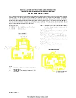
13402 WIRING
TYPICAL CONTACT CONNECTIONS
(TRANSFERS ON ZONE ALARM)
RATED 2 AMP @ 30 VDC
OR .5 AMP @ 30 VAC
Not Supervised
For Powerlimited Source
A
O
C
NOTES:
1.)
Units to be installed in accordance with all local
electrical codes.
2.)
Terminal block will accept a maximum of #12
AWG wiring.
Step 1.)
Installation is to be done by qualified personnel
who have thoroughly read and understood this
instruction sheet.
Step
2.)
Disconnect all power into system, including
batteries.
Step 3.)
Attach conduit and run wires as required.
Step 4.)
Mount Alarm Relay Board as shown in Fig. 1,
using four spacers (P/N 942456) to Main Board. If
Remote LED Anuunciator Driver Board is being
mounted also, mount the Driver Board first using
the installation instructions provided with that
board. See Fig. 2 for the mounting of the Alarm
Relay Board.
Step 5.)
Connect wires to fire alarm system control unit as
required.
Step 6.)
Apply power to system.
Step 7.)
Check for proper operation of functions.
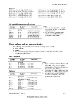
J2 - Silencable / Non-Silencable
Zone Alarm relays only
Non-Silenceable
Positions 1 & 2
Silenceable
Positions 2 & 3
Normal
Disabled
firealarmresources.com


