background image

2

OPERATION

When the 8840/8839 (8840 or 8839) is operating, a sample of air is drawn
from the duct and passed through the sampling chamber by means of the
inlet sampling tube. The air sample passes through the smoke detector
mounted in the duct housing and is exhausted back into the duct through
the outlet sampling tube.

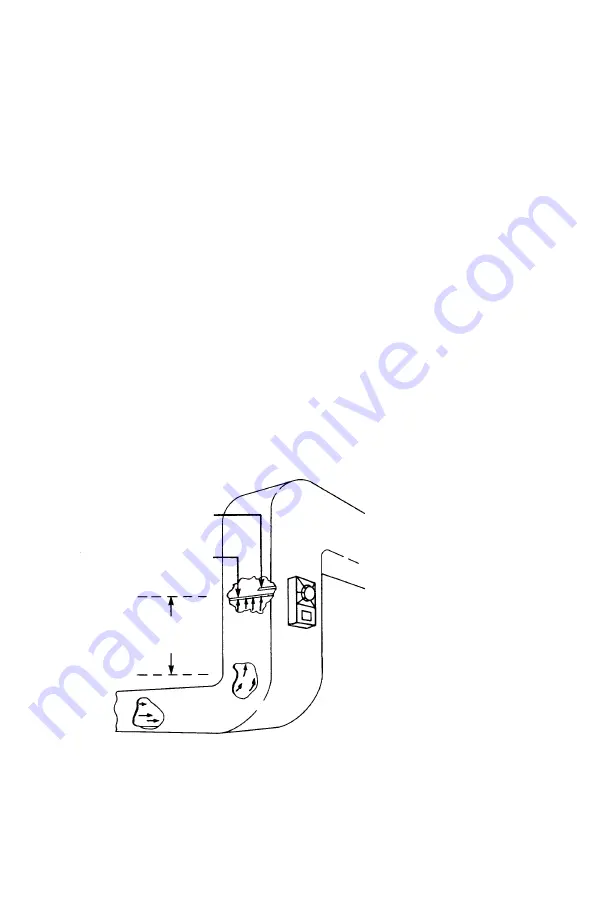
MOUNTING THE AIR DUCT HOUSING
Location on Duct System

Locate the air duct detector in the main supply duct, downstream from the
filters and positioned so as to operate reliably in case of smoke in any part
of the air stream. In instances where filters are capable of removing
smoke, install detectors both upstream and downstream from the filters.

The air duct detectors use sampling tubes which monitor the full width of
an air duct to overcome the limitations of spot-type smoke and heat detec-
tors in the duct. However, since stratification can occur in the air stream
after a long duct run, locate the detector after bends or inlets which create
turbulence, and hence, a more homogeneous mixture of air. The detector
should, when possible, be located a minimum of six duct-widths downstream
from the source of the turbulence (See Figure 1). A 12 inch by 12 inch ac-
cess hole should be cut in the duct adjacent to the detector to permit
checking and cleaning of the sampling tubes, if necessary.

Figure 1

Typical Mounting of Duct

OUTLET
SAMPLING TUBE

INLET
SAMPLING TUBE

AT LEAST
SIX DUCT

WIDTHS

Locate the air duct detector in the air handling system, as shown in Figure
2 and in conformance with NFPA Pamphlet No. 90A, Air Conditioning
and Ventilating System
 and with NFPA 72 Detectors. (Both publications
are available from the National Fire Protection Association, Batterymarch

firealarmresources.com

Summary of Contents for 8839

Page 1: ...40 TECHNICAL DATA TABLE 1 AIR DUCT CONDITIONS Temperature Range 32O F 0O C 100O F 38O C per UL 268 268A Altitude Range 8840 and 8839 No altitude limitations Relative Humidity Range 0 93 non condensating per UL 268 268A Air Duct Velocity Range 300 4000 ft min 8840 and 8839 Sampling Tube Pressure Range of Differences 01 1 0 inches of water column CAUTION These air duct detectors are designed for det...

Page 2: ... overcome the limitations of spot type smoke and heat detec tors in the duct However since stratification can occur in the air stream after a long duct run locate the detector after bends or inlets which create turbulence and hence a more homogeneous mixture of air The detector should when possible be located a minimum of six duct widths downstream from the source of the turbulence See Figure 1 A ...

Page 3: ... the back of the detector housing 2 so that the larger hole on the gasket lines up with the sam pling tube hole on the sampling chamber and the smaller hole lines up with the housing mounting hole b Affix the adhesive backed template 5 to the side of the ductwork c Drill the four 0 110 diameter holes with a No 35 drill bit and cut or punch out two 7 8 inch diameter holes as indicated on the templa...

Page 4: ...4 Figure 3 Exploded View firealarmresources com ...

Page 5: ...mpling tube at the job site as described below TABLE 2 SAMPLING TUBE SELECTION CHART Sampling Tube Standard Outside Duct Width Model No Tube Length 1 ft 93 4 in or less 8932 2 ft 1 ft 93 4 in 3 ft 33 4 in 8933 3 ft 6 in 3 ft 33 4 in 6 ft 33 4 in or less 8934 6 ft 6 in 6 ft 33 4 in 9 ft 93 4 in or less 8935 10 ft Greater than 9 ft 93 4 in Consult factory Note Each model is manufactured with a diffe...

Page 6: ...the inlet tube 3 by inserting it through the air sampling chamber as shown in Figure 3 Face sampling tube holes into the air stream Figure 4 and secure to the housing with 8 32 screws 12 d Install the outlet tube 4 by inserting it into the upper socket of the air sampling chamber with the scarfed end facing downstream See Figure 4 Secure the bracket to the housing with an 8 32 screw e Make sure no...

Page 7: ...7 Figure 5 Typical Connections for the 8840 8839 firealarmresources com ...

Page 8: ...and local codes 3 Refer to the 8717 Installation Instructions P N 315 033280FA 4 Refer to the 8727W 8727C Installation Instructions P N 315 033230FA TB 1 TB 2 TB 3 4 3 2 1 5 5 6 7 8 9 10 11 5 5 6 7 8 9 10 11 8710 8710 8710 MODEL 8840 SEE NOTE 3 MODEL 8717 WITH RELAY MODULE MODEL 8717 WITH RELAY MODULE NOT USED TERMINAL BLOCK WIRE NUT REQUIRED NOT USED NOT USED RELAY BOARD ALARM CONTACTS 125 VAC 24...

Page 9: ...nnected to the base or air duct hous ing that were compatible with the old detector may not be compatible with the new detector Always read the Installation Instructions accompanying the detector to determine detector and accessory compatibility INSTALLATION OF SMOKE DETECTORS CAUTION Faraday Air Duct Detector Model 8839 is designed only for use with the 8854 detector with the 8851 base adapter Fa...

Page 10: ...en snugly but not so tightly as to warp the cover and cause air leakage around the edges of the cover LED Indicator Operation The 8840 contains an LED indicator capable of flashing either one of three distinct colors green yellow or red Every seven seconds the microproces sor based detector checks the following for smoke in its sensing chamber that its smoke sensitivity is within the range indicat...

Page 11: ...s impaired It is recommended that the sam pling tubes be checked and cleaned periodically The detector mainte nance program should consist of periodic cleaning of dust from the detec tor head by using a vacuum cleaner For cleaning Model 8854 refer to the related Installation Instructions The cleaning and test program is recommended for 6 month intervals or more frequently if needed depending on th...

Page 12: ... LW 400 P N 315 092430FA 4 LWZE 4A LW 401 P N 315 096018FA 2 8840 USING 8710 DETECTOR Equipment Installation Wiring Compatibility Identifier Instructions MPC 6000 P N 315 447309 1 The detector model number is the compatibility identifier Do not use 8839 or detector operated accessories with CIDI DD DB or LW 400 P N 315 095659FA 3 8 Fernwood Road Florham Park New Jersey 07932 COMPATIBLE CONTROL EQU...

Reviews: