13400 Owner’s Manual
P/N 446613 Issue I Rev. A
IV-1
Section IV : Configuration
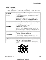
This section provides a checklist for you to consider as you plan the setup of 13400. It
also describes the switches and jumpers you can use to configure operation.
Planning 13400 Configuration
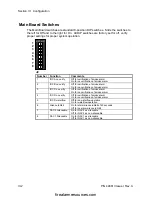
You can use this checklist to help you plan your 13400 configuration. The checklist
provides some reminders about different configurations you might select. Charts
showing switch selections appear on the following pages.
❏
The initiating device circuit needs to be set for alarm verification. Set the
appropriate zone no verify switch to the OFF position.
(J2.1, J2.2, J2.3, J2.4)
❏
The initiating device circuit D has been wired as a waterflow zone. Set the
appropriate zone waterflow switch to the ON position.
(J2.5)
❏
The panel needs to be set up to inhibit the operation of the alarm silence
switch. Set the alarm silence inhibit switch to the ON position.
(J2.6)
❏
The notification appliance circuit needs to be set up as a non-silencable circuit.
Set the notification appliance circuit silencable switch to the ON position.
(J2.7, J2.8)
Servicing Configurations
❏
The initiating device circuit needs to be disabled temporarily from the panel.
Refer to Section II Disable Zones/Signals.
❏
The alarm relays need to be disabled temporarily from basic panel operation.
Press the City Tie Disable button.
❏
The City Tie needs to be temporarily disabled from basic panel operation. Set
the City Tie disable switch on the City Tie Board to the disabled position or press th
City Tie Disable button on the Operator Interface Board on the door.
firealarmresources.com

