background image

General  Information 

measured,  the  operator  is  prohibited  from  touching  the  input 

terminal that is not in service. 

* When the voltage  measured exceeds 60Vdc or  30Vac (valid value),

the operator shall be careful enough to avoid electric shock.

* When  making  measurement  with  a  test  lead,  place  your  fingers

behind its protective ring.

* When switching to another measuring range, be sure that test lead

has already been taken off the measured circuit.

*

For all DC functions, to prevent potential electric shock as a result of

incorrect  reading,  please  first  use  AC  functions  to  check  the

absence  of  any  AV  voltage.  Then,  select  DC  voltage  measuring

range equivalent to or greater than that for AC voltage.

*

Before the tests on electric resistance, diode, capacitor or continuity,

the  operator  must  cut  off  the  power  supply  to  the  circuit  to  be

measured,  and  discharge  all  high-voltage  capacitors  within  the

circuit to be measured.

*

The  eiectric  resistance  measurement  or  continuity  test  cannot  be

carried out in any live electrical circuit.

*

Before  the  current  measurement,  the  operator  must  first  examine

the  protective tube  of the  meter.  Before  connecting  the  meter  to

the  circuit  to  be  measured,  the  operator  must  first  power  off  the

aforesaid circuit.

*

Before repairing  TV  sets  or  measuring  power  switching  circuit,  the

operator must be careful enough to prevent high amplitude voltage

impulse from damaging the meter.

*

This meter uses 4 x 1.SV AA batteries that must be correctly installed

into the battery compartment.

*

When 

F+1 

appears, the batteries must be replaced immediately. The

low level of a battery  will result in incorrect  reading on  the meter,

which  is  likely  to  bring  electric  shock  or  personal  injury  to  the

operator.

*

In measurement,  category III voltage and category  IV  voltage shall

not exceed 1000V and 600V respectively.

* The  meter  shall  not  be  in  service  if  its  case  (or  part  of  its  case)  is

dismantled.

Summary of Contents for FDM18A

Page 1: ...USERS MANUAL 1i AMADIGI TRUE RMS MULTIMETER t afili DmfJ m m fflo1 8 100 10 ill LI LI LI B MkQHz amAVF C F...

Page 2: ...5 Physical appearance 5 2 2 Description of the symbols on the display unit 6 2 3 Description of functional keys 7 2 4 Description of input socket 8 2 5 Accessories 8 3 Operational guidelines 9 3 1 No...

Page 3: ...ameters 15 4 1 Overall parameters 15 4 2 Precision indicator 16 4 2 1 DC voltage 16 4 2 2 AC voltage 17 4 2 3 Frequency 17 4 2 4 Electric resistance 17 4 2 5 Diode 18 4 2 6 Beeper continuity 18 4 2 7...

Page 4: ...accompanies the meter Before operating this meter ensure that the test lead is flawless 1 1 2 Safety considerations When the meter is used in the vicinity of the equipment that produces strong electro...

Page 5: ...all high voltage capacitors within the circuit to be measured The eiectric resistance measurement or continuity test cannot be carried out in any live electrical circuit Before the current measuremen...

Page 6: ...European Union Directive High voltage warning CAT ID over voltage protection 1000V CAT IV over voltage protection 600V 1 1 4 Maintenance practices for safety The operator must first pull out the test...

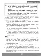
Page 7: ...an sustain the maximum input voltage of 1000V DC or 750V AC at the moment of voltage measurement The meter can sustain the maximum AC voltage of 600V or equivalent voltage valid value when the tests o...

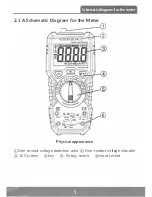
Page 8: ...li c J CJ c J A 1000YCATlll I A eooYCA T IV_ ___ 1 QA IIAX10A IIAX o l ff FUSED 7S N VQHz 10 1000V OM A IIAX600mA t FUSED Physical appearance Non contact voltage detection area Non contact voltage ind...

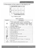
Page 9: ...jury as a result of incorrect reading promptly replace the battery when the battery under voltage indicator appears C Auto power off indicator High voltage warning Negative input polarity indicator AC...

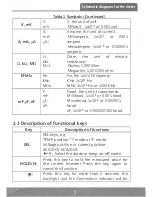
Page 10: ...y KHz lx103 Hz MHz lx106 Hz or 1000 KHz Farad the unit of capacitance Millifarad lxl0 3 or 0 001 farad Microfarad lxl0 6 or 0 000001 farad nF lxl0 9 or 0 000000001 farad 2 3 Description of functional...

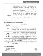
Page 11: ...ription of input socket input Description socket All public input terminals to be measured are COM connected to test leads in black or the public output plugs of exclusive multi function test sockets...

Page 12: ...ccess measurement results even if he is in a darker place The backlight function can be enabled or disabled by the steps below 1 Long press key for more than 2 seconds to enable backlight and illumina...

Page 13: ...and V input socket respectively 3 Use another two ends of the test lead to measure the voltage of the circuit to be measured In parallel connection with the circuit to be measured 4 Read the measured...

Page 14: ...ric resistance of the circuit to be measured 4 Read the measured electric resistance value on LCD screen Notes The measured value of the electric resistance of the circuit differs a bit from the rated...

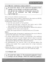
Page 15: ...as voltage reading depend on the variation in electric resistance of other channels between two pen shaped meters 3 2 4 Beep continuity test To avoid the meter or the measured equipment from damage do...

Page 16: ...Use another two ends of the test lead to measure the capacitance of the capacitor to be measured and capture the measured value on LCD screen Notes The measurement of a large capacitance requires a gi...

Page 17: ...g ranges as follows 60 A 600 A 6mA 60 00mA 600 0mA and 10 00A and AC current measuring ranges 60 A 600 A 6mA 60 0mA 600 0mA and 10 00A Measurement of current 1 Turn the rotary switch to the appropriat...

Page 18: ...gn insulation thickness and type 2 When the voltage is input into the meter s input terminal the voltage sensor LED may be on as a result of induced voltage 3 External sources of interference like fla...

Page 19: ...nge indication the LCD screen will display OL Battery Low indication F I will appear when the battery s voltage is below the normal working voltage Input polarity indication will automatically appear...

Page 20: ...suring range 9 999Hz 99 99Hz 999 9Hz 9 999KHz 99 99KHz 999 9KHz 9 999MHz Resolution Accuracy 0 001Hz O OlHz O lHz 0 001 KHz 1 Reading 3 digits 0 01 KHz 0 1 KHz 0 001MHz Input voltage range 200mV 10V a...

Page 21: ...he diode s voltage drop Overload protection 600V DC AC 4 2 6 B eeper continuity Functi Measur Resolution ans 1ng range 01 Goon O ln Description When the built in beeper sounds and the accompanying red...

Page 22: ...ding 3 digits 5 0 Readinq 3 diaits Accuracy 0 8 Reading 3 digits 1 2 Readinq 3 diqits Overload protection protective tube for mA measuring range FF600mA 2 SOV protective tube for lOA measuring range F...

Page 23: ...ement shall not be over 10 seconds The current measurement shall be carried out 1 minute after the completion of previous measurement Frequency response 40Hz lkHz True RMS 4 2 10 Ti t empera ure Measu...

Page 24: ...ent the socket vulnerable to dampness from pollution 5 2 Battery fuse replacement To avoid any electric shock or personal injury as a result of incorrect reading replace batteries once the symbol 1 I...

Page 25: ...6 Make replacements with new 4x 1 5 V AA batteries or new protective tubes 7 Remount the battery cover and fix a bolt 22 _ r...

Page 26: ...EMC LVD YO 1 04 0154...
Reviews: