background image


USE AND MAINTENANCE MANUAL - SECTION 2 


AERIAL PLATFORM ZP 

– Rev. 05_2018 

Page 2-7 


Maximum hydraulic system 
pressure: 

115 bar 

115 bar 

Capacity of the hydraulic tank: 

~ 9 Litres 

Power supply 


Standard 


Optional


220/230 V 50/60 Hz 

2 Batteries AGM 12V 85 Ah 

Operators inside the work 
platform:


Maximum capacity in the work 
platform: 

150 kg 

200 kg 

Maximum operating height: 

(from the ground to the floor of the 
work platform)


10.00 m 

Internal dimensions of the work 
platform: 

~ 61 cm x 61 cm 

~ 61 cm x 100 cm 


MODEL ZP 14 GENERAL 

TECHNICAL DATA 

150 

200 


Internal 

Use 


Outdoor 

Use 


Internal 

Use 


Outdoor 

Use 

Weight of the machine:

 (Total) 

583 kg 

611 kg 

618 kg 

686 kg 

Stabiliser weight: 

14 kg 

21 kg 

21 kg 

38 kg 

Machine height: 

(in transport 

position) 

296 cm 

Maximum resting pressure on 
the ground: 

per wheel/stabiliser 

(*) 

260 daN 

270 daN 

290 daN 

310 daN 

Maximum gradeability:

 (in 

transport position) 

15% - 9° 

Maximum longitudinal work 
slope: 

Base “LEVEL” 

Maximum transversal work 
slope: 

Base “LEVEL” 

Machine base with stabilisers: 

(length x width) 

172x172 

cm 

300x300 

cm 

300x300 

cm 

500x500 

cm 

Machine base without 
stabilisers: 

(length x width) 

136.5 cm x 80 cm 

Summary of Contents for ZP8

Page 1: ...4 ZP16 USE AND MAINTENANCE INSTRUCTIONS TRANSLATION OF THE ORIGINAL INSTRUCTIONS This document is the property of Faraone Industrie Spa Any total or partial reproduction without written authorisation by the author or owner is forbidden ...

Page 2: ...RAL TECHNICAL DATA 2 4 MODEL ZP 10 GENERAL TECHNICAL DATA 2 5 MODEL ZP 12 GENERAL TECHNICAL DATA 2 6 MODEL ZP 14 GENERAL TECHNICAL DATA 2 7 MODEL ZP 16 GENERAL TECHNICAL DATA 2 8 BASIC CONSTRUCTIVE DATA 2 10 SECTION 3 PREPARATION AND INSPECTION 3 1 PERSONNEL TRAINING 3 1 FUNCTIONAL TEST 3 3 SAFETY WARNINGS FOR OPERATORS 3 4 SECTION 4 CONTROLS WARNING LIGHTS AND MACHINE OPERATION4 1 INTRODUCTION 4 ...

Page 3: ...SECTION 8 MAINTENANCE OPERATING INSTRUCTIONS 8 1 BATTERY MAINTENANCE 8 1 HYDRAULIC OIL CHANGE 8 3 CHECKS ON LIFTING CHAINS 8 4 SECTION 9 ATTACHED DOCUMENTATION 9 1 ATTACHMENT 1 Layout for decal application 9 2 ATTACHMENT 2 ZP version 24 V hydraulic diagram 9 4 ATTACHMENT 3 ZP version 220 230 V hydraulic diagram 9 5 ATTACHMENT 4 ZP version 24 V wiring diagram 9 6 ATTACHMENT 5 ZP version 24 V with 2...

Page 4: ...ch it has been manufactured All information in this manual must be read and understood before making any attempt to operate the machine THIS MANUAL IS VERY IMPORTANT DOCUMENTATION ALWAYS KEEP IT NEAR THE MACHINE Due to continuous improvements to the products Faraone Industrie Spa reserves the right to amend the technical data without any prior notice For updated information contact Faraone Industr...

Page 5: ...rm A machine intended to move persons to their work position where they carry out their tasks from the work platform Work platform A platform or basket that is moved to the required work position loaded and from which the operator is able to carry out construction repairs inspections or other similar operations Outriggers Devices used to stabilise the mobile work lift platform supporting and level...

Page 6: ...hone or fax number of the person making the enquiry Accurate description of the problem or of the information to be provided The warranty period is 12 twelve months from the date of the purchase invoice Said warranty covers faulty components and the labour required for servicing if this is carried out at the Manufacturer s premises Transport of the machine is at the purchaser s expense The warrant...

Page 7: ...port commissioning of the same to the local department of INAIL National Institute for the Prevention of Accidents at Work They must also arrange for the machine to undergo ANNUAL inspection of its actual condition and working order For machines sold in other countries The owner of the machine must ascertain whether installation of the machine needs to be reported and or any need for periodic insp...

Page 8: ...a maintenance schedule based on the information provided in this manual which must be strictly complied with The owner user operator company granting in leasing person receiving in leasing the machine must not accept responsibility of its operation before having carefully read the manual and completed the training and the functioning procedures guided by an experienced and skilled operator For fur...

Page 9: ...ndustrie Spa All operational personnel must familiarise with the emergency controls and operation of the machine as specified in the manual Carefully read and comply with all company local and government regulations in force relating to machine operation Inspection of the work place Before using the machine the operator must take the necessary precautions to avoid any hazard in the work place Do n...

Page 10: ...ng carried out all assistance and maintenance set out in the requirements specified in this manual Make sure all safety devices work properly Any changes to such devices constitute a breach of the safety regulations Do not operate the machine if its signs or decals indicating the safety regulations or instructions are illegible or missing Avoid building up debris on the floor of the machine Preven...

Page 11: ...and even pressure If there are people on the work platform allow personnel to operate the machine from the ground exclusively in the event of an emergency Completely lower the extending structure and disconnect the power supply before leaving the machine unattended When welding is carried out from the machine take precautions to protect all machine components from contact with sprays generated by ...

Page 12: ...t or one hand and both feet are continuously in contact with the machine when entering and exiting Electrocution hazard Maintain a distance of at least 3 m between the machine parts and the occupants with their tools and equipment and an electric line or equipment having an electric charge of up to 50 000 Volt 0 3 m must be added for every increment equal to or less than 30 000 Volt Voltage range ...

Page 13: ...illed person in accordance with the company local and government regulations concerning work carried out near live equipment Tilting hazard Do not lift the work platform on a slope or on irregular or soft surfaces Before driving the machine on floors bridges lorries and other surfaces check their maximum capacity Do not exceed the maximum capacity of the machine Distribute the loads on the floor o...

Page 14: ... stabilisers inserted and the extendible structure lifted Before moving the machine completely lower the extending structure Crushing and impact hazard When using the machine or lifting or lowering the work platform check the distances above at the sides and below the platform Do not lean over the rails of the work platform when the machine is in operation Always pay the utmost attention to preven...

Page 15: ...d unload it Refer to the Emergency procedures section in this manual Before towing lifting and transport ensure the work platform is completely retracted and emptied Do not pull or push a blocked or disabled machine While lifting the machine by means of a forklift place the forks exclusively in the appropriate areas of the machine Lift by means of lifting equipment of adequate capacity For informa...

Page 16: ...G MACHINE INTENDED TO MOVE PERSONS TO THEIR WORK POSITIONS ON THE WORK PLATFORM THE ELEVATING PLATFORM ZP MUST BE USED ONLY FOR ITS INTENDED PURPOSES ANY OTHER USE IS CONSIDERED MISUSE ATTENTION THE USER MUST OBTAIN APPROVAL AND GUIDELINES FROM THE MANUFACTURER ON SPECIAL OPERATING METHODS OR CONDITIONS NOT COVERED IN THOSE SPECIFIED BY THE MANUFACTURER ...

Page 17: ...USE AND MAINTENANCE MANUAL SECTION 2 AERIAL PLATFORM ZP Rev 05_2018 Page 2 2 MACHINE FEATURES H MAX 1 H P H MAX 2 C1 C2 L A B E1 E2 ...

Page 18: ...60 16 mt 14 mt 800 1950 ZP 14 8 mt 10 mt 12 mt 14 mt 800 1950 800 2530 8 mt 6 mt 10 mt 8 mt 12 mt 10 mt 14 mt 12 mt ZP 8 ZP 10 ZP 12 ZP 14 ZP 16 MODEL VERSION H MAX 1 in position E2 H MAX 2 in position E2 L mm H mm A mm B mm C1 mm C2 mm E1 mm E2 mm ZP 8 150 l 8 mt 6 mt 800 1950 670 670 1360 1360 400 1380 150 E 2100 2100 400 1380 ZP 10 150 l 10 mt 8 mt 800 1950 1360 1360 400 1380 150 E 2550 2550 40...

Page 19: ...ne Total 383 kg 395 kg 402 kg 414 kg Stabiliser weight 12 kg 15 kg 15 kg 18 kg Machine height in transport position 195 cm Maximum resting pressure on the ground per wheel stabiliser 185 daN 190 daN 210 daN 215 daN Maximum gradeability in transport position 15 9 Maximum longitudinal work slope Base LEVEL Maximum transversal work slope Base LEVEL Machine base with stabilisers length x width 136x136...

Page 20: ...ght of the machine Total 498 kg 522 kg 517 kg 541 kg Stabiliser weight 12 kg 18 kg 15 kg 21 kg Machine height in transport position 195 cm Maximum resting pressure on the ground per wheel stabiliser 230 daN 235 daN 250 daN 260 daN Maximum gradeability in transport position 15 9 Maximum longitudinal work slope Base LEVEL Maximum transversal work slope Base LEVEL Machine base with stabilisers length...

Page 21: ...ENERAL TECHNICAL DATA 150 200 Internal Use Outdoor Use Internal Use Outdoor Use Weight of the machine Total 531 kg 559 kg 554 kg 634 kg Stabiliser weight 14 kg 21 kg 18 kg 38 kg Machine height in transport position 253 cm Maximum resting pressure on the ground per wheel stabiliser 240 daN 250 daN 265 daN 290 daN Maximum gradeability in transport position 15 9 Maximum longitudinal work slope Base L...

Page 22: ...platform 61 cm x 61 cm 61 cm x 100 cm MODEL ZP 14 GENERAL TECHNICAL DATA 150 200 Internal Use Outdoor Use Internal Use Outdoor Use Weight of the machine Total 583 kg 611 kg 618 kg 686 kg Stabiliser weight 14 kg 21 kg 21 kg 38 kg Machine height in transport position 296 cm Maximum resting pressure on the ground per wheel stabiliser 260 daN 270 daN 290 daN 310 daN Maximum gradeability in transport p...

Page 23: ...platform 12 00 m Internal dimensions of the work platform 61 cm x 61 cm 61 cm x 100 cm MODEL ZP 16 GENERAL TECHNICAL DATA 150 Internal Use Outdoor Use Weight of the machine Total 624 kg 692 kg Stabiliser weight 21 kg 38 kg Machine height in transport position 296 cm Maximum resting pressure on the ground per wheel stabiliser 270 daN 295 daN Maximum gradeability in transport position 15 9 Maximum l...

Page 24: ...ank 9 Litres Power supply Standard Optional 220 230 V 50 60 Hz 2 Batteries AGM 12V 85 Ah Operators inside the work platform 1 Maximum capacity in the work platform 150 kg Maximum operating height from the ground to the floor of the work platform STANDARD position HIGH position 12 00 m 14 00 m Internal dimensions of the work platform 61 cm x 61 cm ...

Page 25: ...tween one profile and another is achieved with chains An oil hydraulic cylinder is installed between the first and second profile powered by the hydraulic unit to lift the structure The chains interconnect the extending structure elements so that they lift simultaneously WORK PLATFORM The work platform is completely constructed in extruded aluminium profiles The tread floor consists of aluminium p...

Page 26: ... AND MAINTENANCE MANUAL SECTION 2 AERIAL PLATFORM ZP Rev 05_2018 Page 2 11 ATTENTION THE AERIAL PLATFORM ZP HAS BEEN TESTED BY THE MANUFACTURER THROUGH STATIC STABILITY TESTS OVERLOAD TESTS OPERATION TESTS ...

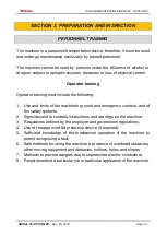
Page 27: ...he following 1 Use and limits of the machine s ground and emergency controls and of the safety systems 2 Signs decals for controls instructions and warnings on the machine 3 Regulations defined by the employer and government regulations 4 Use of the approved fall protection device if required 5 Sufficient knowledge of the mechanical operation of the machine to permit recognising a fault 6 Safe met...

Page 28: ... the trainee is able to safely operate and use the machine Operator responsibility The operator must be trained with regard to responsibility and authority to switch off the machine in the event of fault or other unsafe conditions both relating to the machine and to the work area NOTE the owner shall provide skilled personnel for training both at the time of delivery of the first units and later i...

Page 29: ... below 1 Carry out the operations as instructed from the ground controls without any load in the basket a Operate the ground controls lifting and lowering the work platform b Ensure all machine functions are disabled when operating pressing the emergency stop button c Check correct operation of the manual descent valve 2 Carry out the specified operations from the control console of the cage a Mak...

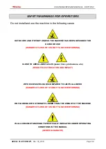
Page 30: ...USE DANGER OF LOSS OF STABILITY AND OVERTURNING CLOSE TO AERIAL OBSTACLES power lines protrusions etc RISK OF ELECTROCUTION AND IMPACT WITH EXCESSIVE LOADS COMPARED TO LIMITS ALLOWED DANGER OF LOSS OF STABILITY AND OVERTURNING ON FLOORING WITH STRENGTH LOWER THAN THE WEIGHT OF THE MACHINE DANGER OF LOSS OF STABILITY AND OVERTURNING IN ALL CIRCUMSTANCES NOT SPECIFICALLY INDICATED UNDER OPERATING CO...

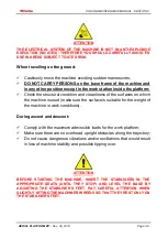
Page 31: ...eanliness of the surfaces on which the machine is used make sure the surface is suitable for the weight of the machine in work conditions During ascent and descent Comply with the maximum admissible loads for the work platform Make sure there are no overhead upright obstacles along the trajectory Do not cause dangerous vibrations and or oscillations that would result in loss of machine stability a...

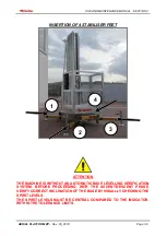
Page 32: ...EET ATTENTION THE MACHINE IS WITHOUT AN AUTOMATIC BASE LEVELLING VERIFICATION SYSTEM BEFORE PROCEEDING WITH THE ASCENT DESCENT PHASE VERIFY CORRECT INCLINATION OF THE BASE BY VISUALLY CHECKING THE SPIRIT LEVELS THE SPIRIT LEVELS MUST BE CENTRAL COMPARED TO THE INDICATOR WITHIN THE TOLERANCE LIMITS 1 4 3 2 ...

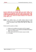
Page 33: ...S FROM THE GROUND ENABLING THE TELESCOPIC STRUCTURE TO LIFT NOTE If the machine base is not raised enough during the initial stabilisation phase and the wheel for checking that the base is lifted is still on the ground when trying to lift the cage the machine will not lift Restore machine operation as follows 1 Make sure the stabilisers are properly and fully engaged 2 Raise the stabilisers until ...

Page 34: ...USE AND MAINTENANCE MANUAL SECTION 3 AERIAL PLATFORM ZP Rev 05_2018 Page 3 8 ATTENTION CHECK THE POSITION OF THE SPIRIT LEVELS ...

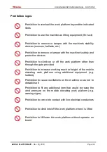
Page 35: ...n to climb on or off the work platform other than through the gate provided Prohibition to increase working reach or height of the mobile elevating work platform using additional equipment e g ladders Prohibition to cause oscillations on the machine so as not to destabilise it Prohibition to fit any additional item that would increase the wind pressure on the mobile elevating work platform e g war...

Page 36: ...RIED OUT BY THE EMPLOYER ATTENTION ANY FENCING ENCLOSING THE MACHINE S WORK AREA AND ANY ADDITIONAL SAFETY SIGNS TO BE USED FOR THAT AREA MUST BE VERIFIED BASED ON THE SPECIFIC RISK ASSESSMENT CARRIED OUT BY THE EMPLOYER ATTENTION REGARDING ITALIAN LEGISLATION ITALIAN LEGISLATIVE DECREE 81 2008 REQUIRES THE USE OF SUITABLE SAFETY BELTS FOR ALL EXTENDING DECKS AND SIMILAR EQUIPMENT THIS MEASURE ALS...

Page 37: ...USE AND MAINTENANCE MANUAL SECTION 3 AERIAL PLATFORM ZP Rev 05_2018 Page 3 11 RETAINING ONLY 1 PERSON ...

Page 38: ...ONS FROM WHERE THEY CAN CARRY OUT THEIR TASKS FROM THE WORK PLATFORM The main control station is located on the work platform The operator can lift and lower the work platform from the work platform control console the machine is not equipped with self propelling therefore shifting is by manual pushing allowed only when the work platform is at the lowest position If the operator on the work platfo...

Page 39: ...station must be switched on Both emergency stop switches one located on the ground control station and the other on the control desk of the work platform must be in RESET position 24 V BATTERY POWER SUPPLY If the machine is equipped with batteries there is a battery charger with AC input DC output The battery charger automatically stops charging when the batteries are fully charged ATTENTION KEEP ...

Page 40: ...RED LED when charging the battery indicates the beginning of the charging cycle Charging stops automatically with no need for operator action and is indicated by a GREEN LED on While using the machine battery charge will change from fully charged indicated by the green LED to partially charged indicated by the orange LED to low battery indicated by the red LED Carry out the following operations ca...

Page 41: ...T BE COMPLETELY AND EVENLY CHARGED AT LEAST ONCE A WEEK AND STORED UNPLUGGED TO STOP THEM FROM GOING FLAT 220 230 V POWER SUPPLY If the machine is equipped with a plug connecting it to a 220 230 V 50 60 Hz system to power the machine it is sufficient to connect the power plug to an external electrical system ATTENTION CONNECT THE MACHINE TO A POWER SYSTEM THAT IS COMPLIANT WITH THE APPLICABLE LAW ...

Page 42: ...ev 05_2018 Page 4 5 GROUND CONTROL STATION FOR 220 230 V POWERED MACHINES Push button panel details FOR 24 V POWERED MACHINES Push button panel details FOR 24 V POWERED MACHINES EQUIPPED WITH 220 230 V SOCKET ON BOARD THE WORK PLATFORM 1 4 2 3 5 2 2 3 4 6 6 3 ...

Page 43: ...from the ground control desk the following conditions of the controls must be met Ground control station The main power supply switch must be switched on Ground control station The Emergency stop switch off button must be in RESET position POWER SUPPLY CONNECTED Work platform desk The emergency stop switch off button must be in RESET position POWER SUPPLY CONNECTED Emergency stop switch off button...

Page 44: ...gency stop POWER SUPPLY CONNECTION PULL OUTWARDS to restore the emergency stop Ascent descent control button a ASCENT of the work platform b DESCENT of the work platform ATTENTION BEFORE LIFTING THE WORK PLATFORM PAY ATTENTION TO WHAT IS STATED IN SECTION 3 PREPARATION AND INSPECTION WITH REGARD TO THE BASE LEVELLING CONTROL SYSTEM a b ...

Page 45: ...breaker switch acts as the machine s main power switch and as a protection against power surges on the electrical mains to which the machine is connected or against malfunctions that may arise on the machine s electrical system Move the lever switch upwards to switch it on Move it downwards to cut the machine s power off For a 220 230 V powered machine the switch acts as the main power switch for ...

Page 46: ...g the machine from the control console of the work platform it is necessary to satisfy the following conditions of the controls Ground control station The main power supply switch must be switched on Ground control station The Emergency stop switch off button must be in RESET position POWER SUPPLY CONNECTED Work platform desk The emergency stop switch off button must be in RESET position POWER SUP...

Page 47: ...he machine to operate the emergency stop switch off button on the machine must be in RESET position POWER SUPPLY DISCONNECTION PUSH INWARDS to engage the emergency stop POWER SUPPLY CONNECTION PULL OUTWARDS to restore the emergency stop Ascent descent control button a ASCENT of the work platform b DESCENT of the work platform a b ...

Page 48: ...ASE BY ADJUSTING THE STABILISER S FEET PAY CAREFUL ATTENTION WHEN SLIGHTLY LIFTING THE MACHINE S WHEELS SO THAT THEY REST ONLY ON THE STABILISER S FEET ATTENTION TO PREVENT UNAUTHORISED PERSONNEL FROM USING THE MACHINE S GROUND CONTROL WHILST THE OPERATOR IS INSIDE THE WORK PLATFORM AT A HEIGHT BEFORE CLIMBING INSIDE HE SHE MUST CLOSE THE ACCESS DOOR TO THE GROUND CONTROLS REMOVE THE KEY AND STORE...

Page 49: ...the main power switch off and remove the key that opens the controls door at the base 3 Actuate both the front wheel locking brakes NOTE to unlock the wheel brakes lift the lever with a small flick of the toe ATTENTION do not use your hands ATTENTION PREVENT UNAUTHORISED USE BY SWITCHING OFF THE MACHINE SWITCHING OFF THE MAIN POWER SWITCH AND REMOVING THE KEY THAT OPENS THE CONTROLS DOOR WHEN THE ...

Page 50: ...TFORM CONFIGURATION WORK PLATFORM WITH VERTICAL OPENING SIDE ENTRY Model Maximum capacity Small work platform 150 kg 1 person Large work platform 200 kg 2 people 1 Vertical opening sliding rail 2 Work platform footboard 3 Control console of the machine 4 Safety belt connection 4 3 2 1 4 ...

Page 51: ... STANDARD AND HIGH POSITION IF THE WORK PLATFORM IS INSTALLED IN A HIGH POSITION YOU MUST USE THE LADDER PROVIDED WITH THE MACHINE SITUATED ABOVE THE BASE TO ACCESS THE PLATFORM ATTENTION WHEN THE WORK PLATFORM IS BEING REASSEMBLED MAKE SURE YOU INSERT AND LOCK THE CONNECTING PIN TO THE STRUCTURE OF THE EXTENDIBLE COLUMN 350 2350 HIGH POSITION STANDARD POSITION ...

Page 52: ...FORM ZP Rev 05_2018 Page 4 15 ATTENTION BEFORE CLIMBING UP THE LADDER MAKE SURE THE ANCHORING MECHANISMS ARE FITTED CORRECTLY INTO PLACE WHEN THE MACHINE OPERATOR HAS CLIMBED ON BOARD THE WORK PLATFORM A GROUND OPERATOR WILL NEED TO REMOVE THE LADDER ...

Page 53: ...THE WORK PLATFORM IF THE RAILING ON THE WORK PLATFORM DOES NOT APPEAR TO CLOSE PROPERLY AND HAVE IT REPAIRED CONTACT THE MANUFACTURER IF NECESSARY ATTENTION BEFORE STARTING THE MACHINE INSERT THE STABILISERS IN THE APPROPRIATE SEATS UNTIL THEY STOP AND LEVEL THE BASE BY ADJUSTING THE STABILISER S FEET PAY CAREFUL ATTENTION WHEN SLIGHTLY LIFTING THE MACHINE S WHEELS SO THAT THEY REST ONLY ON THE ST...

Page 54: ... with the special belts check the gross weight of the machine in the Operational Technical Data Table of the machine By moving it with a forklift check the gross weight of the machine in the Operational Technical Data Table for the machine Using the special manual loading system supplied optionally to quickly load onto the transport vehicle ATTENTION LOAD THE MACHINE ONTO A HEAVY DUTY VEHICLE HAVI...

Page 55: ...AERIAL PLATFORM ZP Rev 05_2018 Page 4 18 Lifting with belts The machine can be lifted with special belts In this case the machine must be held by its upper part with the handles in order to position it in a stable way see following figure ...

Page 56: ...9 Handling with a forklift The machine can be lifted with a forklift truck In this case it must be held from the rear part of the machine in order to position it in a stable way onto the forks see following figure ATTENTION LIFT THE MACHINE ONLY WITH WORK PLATFORM FULLY LOWERED ...

Page 57: ...e can be loaded by means of the provided forklift supplied upon request Phase 1 Move the machine close to the edge of the truck Phase 2 Using the two spring pins position the support trolley at about 10 cm From the height of the truck s loading bed Check that the two spring pins that lock the trolley are correctly hooked when overturning ...

Page 58: ...ase 3 Remove the lever under the machine s base carriage being careful to re insert the spring lock stop Phase 4 Slope the machine until the support trolley s tube touches the truck s bed Then with the pin on the bed start lifting the machine using the lever under the base carriage ...

Page 59: ...eck that the two tilting blocks are released from the support trolley Phase 6 When the platform is in the horizontal position push it on the bed until it touches the back and pull back the overturning lever under the base carriage ATTENTION SECURE THE MACHINE SO THAT IT DOES NOT GET DAMAGED DURING TRANSPORT ...

Page 60: ...llow the previous phases in reverse starting from Phase 6 ATTENTION MAKE SURE THAT THE SLIDING SUPPORT TROLLEY IS POSITIONED AT THE END OF THE GUIDES ON THE PART NEXT TO THE MACHINE S BASE CARRIAGE Pull the machine until the large wheels are out from the truck s bed and resting it on the support trolley turn the machine until it touches the ground ...

Page 61: ...in case of absolute need The machine controls must only be used by qualified personnel INTERRUPT MACHINE ACTIVITY IF THE CONTROLS DO NOT OPERATE CORRECTLY In case of incorrect operation of the controls or power outage the emergency stop must be operated and if necessary a qualified operator must carry out the EMERGENCY DESCENT procedure from the ground Proceed as follows 1 Press the emergency butt...

Page 62: ...ntinuously supervise the entire descent phase of the work platform 5 Once descent is completed tighten the knob again 6 Reset the emergency button to enable the machine s power supply ATTENTION THE OPERATIVE STAGES OF THE EMERGENCY DESCENT PROCEDURE ARE SET OUT ON AN APPROPRIATE DECAL NEAR THE EMERGENCY DESCENT CONTROL 1 ...

Page 63: ... the working platform A crane or forklift may be used to stabilise machine movement REPORTING THE ACCIDENT Faraone Industrie Spa must be immediately informed of any incidents involving a Faraone product Contact the factory by telephone and provide all the necessary details even in case no injuries or evident damage to property are involved ATTENTION AFTER AN ACCIDENT INSPECT THE ENTIRE MACHINE AND...

Page 64: ...THE MACHINE NOTE FOR INSPECTION besides complying with the above criteria ensure for each component that all parts are present securely fixed and not loose and that there are no visible damage leaks or signs of excessive wear a Drive wheels free wheels and swivel castors Check there is no debris on the wheels or around them b Base frame Ensure there are no loose wires or cables hanging underneath ...

Page 65: ... stop switch in the reset position and legible control signs i Ground control station if present Main power supply selection switch operable signs securely fastened and legible emergency stop switch operable j Extendable structure unit Structure profiles sliding inserts chains sequential activation cables pulleys able to turn freely k Spirit levels if present Check the integrity of the spirit leve...

Page 66: ...THE MANUFACTURER ATTENTION CONTACT THE MANUFACTURER IF IN DOUBT OF THE FREQUENCY AND METHOD OF ROUTINE AND OR EXTRAORDINARY MAINTENANCE ACTIVITIES DO NOT TAKE INITIATIVES IF YOU ARE UNSURE OF WHAT YOU ARE DOING ATTENTION TO CARRY OUT MAINTENANCE AND OR CLEANING OPERATIONS ON THE MACHINE THAT REQUIRE THE EXTENDABLE STRUCTURE TO BE IN A PARTIALLY EXTENDED POSITION ANCHOR THE CAGE SAFELY FOR EXAMPLE ...

Page 67: ...integrity of the structural profiles Check correct operation of the emergency descent valve Take the cage to a height and execute an emergency descent as shown in the relative section of this manual Hydraulic Oil Check the level of hydraulic oil and top up if necessary Refer to the specifications described in the relative paragraph for information regarding hydraulic oil checks and top up Check th...

Page 68: ...ains thoroughly before lubricating them The lifting chains must be lubricated with the extendable structure completely closed by gravity from the top directly on the return wheels if necessary temporarily remove the protective cover to access the chains For information regarding the wear of chains refer to Checks on the lifting chains Check the wheels for wear Check there is no debris on the wheel...

Page 69: ... extensions On each runner one of the 3 wheels turns on an adjustable axis This allows the wheels to be adjusted when they are worn thus giving rise to possible play of the moving extendable structure parts Contact the Manufacturer for further information and instructions regarding the adjustment of the sliding wheels of the extendable structure when a backlash anomaly is found MAINTENANCE EVERY T...

Page 70: ...ply 4 Open the protective cover of the battery compartment 5 Loosen the connection terminals of the batteries positive pole and negative pole 6 Remove the batteries and replace them with new ones 7 Connect the terminals of the batteries making sure to do so correctly red wire for the positive pole black wire for the negative pole and tighten them 8 Close and lock the protective cover 9 Position th...

Page 71: ...ULD THE BATTERY BE DAMAGED USE THE RELATIVE PERSONAL PROTECTIVE EQUIPMENT TO PROTECT YOUR HANDS AGAINST CHEMICAL AGGRESSION WHEN REPLACING THE BATTERY DISPOSE OF THE BATTERIES IN ACCORDANCE WITH THE LAWS IN FORCE REPLACE THE BATTERIES WITH THE SAME TYPES AS THOSE SUPPLIED BY THE MANUFACTURER ...

Page 72: ...different makes or types is strongly ill advised since they may not contain the necessary additives or viscosity may be different ATTENTION THE HYDRAULIC OIL MUST BE TOPPED UP CHANGED WITH THE CAGE FULLY DOWN IF THE HYDRAULIC OIL TANK IS UNDER THE CAGE KEEP IT AT A HEIGHT OF APPROXIMATELY ONE METRE AND TOP UP CHANGE IT ATTENTION DISPOSE OF THE WASTE OIL IN ACCORDANCE WITH THE LAWS IN FORCE ...

Page 73: ...an lead to chain fatigue failures 3 Rust on joints Corroded connection points are recognisable by their red brown colour This phenomenon may arise from lack of lubrication or use of grease and oil unsuitable for penetrating the joints 4 Stiff joints Any joint that is not in a straight position when leaving the return pulley can no longer be used This phenomenon may be caused by corrosion or cold m...

Page 74: ...y contribute to this problem 9 Broken pins This problem usually occurs as a result of corrosion in the chain joints Since the pins of a single chain are subject to the same load and corrosion conditions one failure is usually followed by more Experience has shown that this type of failure is not always easily recognised as there are no evident changes in the chain conditions especially in the init...

Page 75: ...otal length Maximum elongation allowed 2 along the most worn section Wear of plate profiles Where the phenomenon is most noticeable maximum permitted height reduction of 2 5 on one side only 4 if on two sides in relation to the initial height Wear on the side of the chain Replace the chain if the protruding part of the pin heads is worn down by more than 25 or if the outer side is worn down by mor...

Page 76: ... OF LIFTING CHAINS 1 CHAIN PAIR 1st EXTENSION 2 CHAIN PAIR 2nd EXTENSION 3 CHAIN PAIR 3rd EXTENSION 4 CHAIN PAIR 4th EXTENSION 5 CHAIN PAIR 5th EXTENSION 6 CENTRAL SUPPORT 7 PULLEY SPACER 8 PULLEY SPACER 9 SIDE SUPPORT 10 SIDE SUPPORT 11 SUPPORT COUPLING PLATE 11 1 2 10 3 4 5 6 7 8 9 ...

Page 77: ...5_2018 Page 8 8 ATTENTION FOR FURTHER INFORMATION REGARDING PURCHASE OF SPARE PARTS AND CONSUMABLES PLEASE CONTACT THE MANUFACTURER THE MANUFACTURER DECLINES ALL LIABILITY DUE TO DAMAGE OR MALFUNCTION CAUSED BY USE OF PARTS NOT AUTHORISED BY THE SAID MANUFACTURER ...

Page 78: ...version 24 V hydraulic diagram ATTACHMENT 3 ZP version 220 230 V hydraulic diagram ATTACHMENT 4 ZP version 24 V wiring diagram ATTACHMENT 5 ZP version 24 V with 220 230 V socket wiring diagram ATTACHMENT 6 ZP version 220 230 V wiring diagram ATTACHMENT 7 Inspection certificate ATTENTION SHOULD THE MACHINE BE TRANSFERRED TO A THIRD PARTY ALL DOCUMENTATION MUST BE DELIVERED WITH IT ...

Page 79: ...d load on the cage 4 INDICATION INSTRUCTIONS FOR CORRECT INSERTION OF THE STABILISERS FEET 5 PROHIBITION SIGN UNAUTHORISED PERSONNEL MUST NOT USE THE MACHINERY 6 OBLIGATION SIGN REFER TO THE OPERATING MANUAL 7 OBLIGATION SIGN WEAR NON SLIP SHOES 8 PROHIBITION SIGN DO NOT REMOVE THE SAFETY GUARDS AND DEVICES 9 INDICATION EMERGENCY DESCENT 10 INDICATION EMERGENCY DESCENT PROCEDURE 11 PLATE MAIN TECH...

Page 80: ...USE AND MAINTENANCE MANUAL SECTION 9 AERIAL PLATFORM ZP Rev 05_2018 Page 9 3 5 6 7 8 14 1 1 1 2 3 10 4 4 9 5 6 7 8 13 5 6 7 8 13 2 3 12 12 4 2 3 4 11 ...

Page 81: ...USE AND MAINTENANCE MANUAL SECTION 9 AERIAL PLATFORM ZP Rev 05_2018 Page 9 4 ATTACHMENT 2 ZP version 24 V hydraulic diagram ...

Page 82: ...USE AND MAINTENANCE MANUAL SECTION 9 AERIAL PLATFORM ZP Rev 05_2018 Page 9 5 ATTACHMENT 3 ZP version 220 230 V hydraulic diagram ...

Page 83: ...USE AND MAINTENANCE MANUAL SECTION 9 AERIAL PLATFORM ZP Rev 05_2018 Page 9 6 ATTACHMENT 4 ZP version 24 V wiring diagram ...

Page 84: ...USE AND MAINTENANCE MANUAL SECTION 9 AERIAL PLATFORM ZP Rev 05_2018 Page 9 7 ...

Page 85: ...USE AND MAINTENANCE MANUAL SECTION 9 AERIAL PLATFORM ZP Rev 05_2018 Page 9 8 ATTACHMENT 5 ZP version 24 V with 220 230 V socket wiring diagram ...

Page 86: ...USE AND MAINTENANCE MANUAL SECTION 9 AERIAL PLATFORM ZP Rev 05_2018 Page 9 9 ...

Page 87: ...USE AND MAINTENANCE MANUAL SECTION 9 AERIAL PLATFORM ZP Rev 05_2018 Page 9 10 ATTACHMENT 6 ZP version 220 230 V wiring diagram ...

Page 88: ...USE AND MAINTENANCE MANUAL SECTION 9 AERIAL PLATFORM ZP Rev 05_2018 Page 9 11 ...

Page 89: ...e 9 12 ATTACHMENT 7 Inspection certificate ELEVATING PLATFORM ZP8 ZP10 ZP12 ZP14 ZP16 Serial number The machine constructed in conformity with the type testing model underwent the following tests Brake test Overload test Operation test With a POSITIVE outcome Tortoreto on ...

Page 90: ...NOTES ...

Page 91: ......

Page 92: ...Faraone Industrie Spa Contrada Salino Via San Giovanni 20 64018 Tortoreto TE ITALY Tel 39 0861 77 22 21 fax 39 0861 77 22 22 www faraone com info faraone com ...

Reviews: