background image

FFD1.DS4

8

440V MODELS

1

2

3

4

5

6

A

A

4

13

14

11

10

A

B

K

M

D

E

6

22

A

B

23

12

32

21

27

K

30

29

A

B

16

20

15

SUPPLIED
WITH ITEM 11

5

26

3

2

28

P

N

A

B

C

17

18

19

K

1

9

M

31

24

28

M

7

B

M

J

P1

8

7

6

5

4

3

2

1

SPEEDPOT LO (orange lead)

SPEEDPOT WIPER (red lead)

SPEEDPOT HI (white lead)

+ FIELD (+F)

- ARMATURE / - FIELD (-A/-F)

+ ARMATURE (+A)

VAC INPUT (AC)

VAC INPUT (AC)

SCR CONTROL

BOARD

HOOK-UP

MIN

MAX

IR

LIM

A - A

VIEW

Item
1
2
3
4
5
6
7
8
9
10
11
12
13
14
15
16
17
18
19
20
21

Part No.
36-094
401-1663-4
22-018
22-018
23-019
25-056
53-007
47-011
50-007s
43-006
044-1102-1
23-007
45-016
45-016-1
35-005
26-075
37-008
47-001
50-004
53-011
067-1112-1

Description . . . . . . . . . . . .
Control box weldment  . . . .
Control box cover . . . . . . . .
Gasket, PVC foam  . . . . . . .
Spring latch  . . . . . . . . . . . .
Control box mounting brkt.  .
Ground lug . . . . . . . . . . . . .
Double fuse holder . . . . . . .
Fuse, 5A 600V . . . . . . . . . .
Transformer, 1.5KVA  . . . . .
Motor control board  . . . . . .
Knob  . . . . . . . . . . . . . . . . .
Terminal strip  . . . . . . . . . . .
Terminal strip marker  . . . . .
Indicator light, 250V red  . . .
Toggle switch DPST . . . . . .
Fuse block spacer  . . . . . . .
Fuse block, double . . . . . . .
Fuse, 8A 250V . . . . . . . . . .
Boot . . . . . . . . . . . . . . . . . .
O ring  . . . . . . . . . . . . . . . .

X
1
1
2
2
1
1
1
1
2
1
1
1
1
1
1
1
2
1
2
1
1

Item
22
23
24
25
26
27
28
29
30
31
P
N
M
K
J
F
E
D
C
B
A

Part No.
48-013-3
22-022
- - -
53-002-2 
420-1136-1
16-002
54-005-3
420-2019-8
420-1086-8
420-1135-3
- - -
- - -
- - -
- - -
- - -
- - -
- - -
- - -
- - -
- - -
- - -

Description . . . . . . . . . . . .
Plastic plug  . . . . . . . . . . . .
O ring  . . . . . . . . . . . . . . . .
Decal, 440V . . . . . . . . . . . .
Wire nut, yellow  . . . . . . . . .
Decal, wiring diagram  . . . .
Rubber gromet . . . . . . . . . .
Insulated clamp  . . . . . . . . .
Decal, warning . . . . . . . . . .
Decal, FFD-3000VS . . . . . .
Decal, L1 & L2 . . . . . . . . . .
#10-32 Hex nut  . . . . . . . . .
#10-32 x ½ lg RHMS  . . . . .
#8 x 3/8 lg Pan hd self tap  B
#6 x 3 1/2 lg Pan hd self tap  B
#6 x 5/8 lg Round hd screw  F
#10 x ½ lg Pan hd self tap  A
5/16 Flat washer  . . . . . . . .
5/16 x 3/4 lg. Type A hex head
1/4 Flat washer  . . . . . . . . .
1/4 -20 ESNA hex nut  . . . .
1/4-20 x 3/4 hex head screw

X
1
1
1
4
1
1
3
1
1
1
1
1
12
2
2
1
4
4
2
5
5

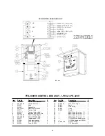
FFD-3000VS CONTROL BOX ASSY., 3-PH 440V

Summary of Contents for SCATTERGRAIN FFD-3000VS

Page 1: ...INSTALLATION and OPERATION MANUAL Model FFD 3000VS SCATTERGRAIN Bulletin FFD VS 02 2 ...

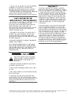
Page 2: ...ower supply disconnect switch and lock it in the open position using a padlock before performing any service or maintenance work It is highly recommended that each worker have his own lock and key WARRANTY Farm Fans a divisionof ffi Corporation warrants its products to be free of defects in material and workman ship The only obligation of the manufacturer is to repair or replace products which hav...

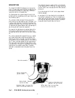
Page 3: ... rotated within the U bolt slots at the T drive to provide limited tilt in the second plane This compound angle allows the thrower blade to have a variable bite on the grain The adjustable center open ings provide for controlled center filling The blade extension is adjustable to allow the grain throw to be varied The standard hangers supplied with the unit will adjust to roof openings of 21 to 30...

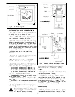
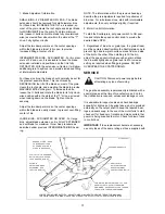
Page 4: ...nect the POWER SUPPLY as listed A 220V models Connect wires L1 and L2 to con trol box terminal numbers 1 and 2 A 440V models Connect wires L1 and L2 to the primary fuses B Connect ground wire to ground lug within control box 8 Recheck all wires to ensure they are properly con nected and tightened CAUTION Improper installation of this control may cause injury to personnel or control fail ure THE CO...

Page 5: ...t with intermediate adjustments then vary settings slightly if required 2 Motor Control Information To start the Scattergrain set power switch to ON posi tion and rotate the speed control knob to provide the desired blade RPM 3 Regardless of bin size or grain type the grain stream must be centered directly within the Scattergrain cone to prevent high and low grain surface areas from one side of th...

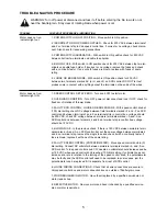
Page 6: ...ER SUPPLY 440 VOLTS GREEN PRIMARY FUSES 5 AMP L2 L1 H1 H2 H3 H4 TRANSFORMER 440V TO 220V 1 5 KVA X1 X2 X3 X4 SCR CONTROL BOARD SECONDARY FUSES 8 AMP AC AC A F F A R PROPER FUSE SIZE AND TYPE IS CRITICAL SEE INSTALLATION MANUAL FOR REQUIREMENTS FFD2 DS4 HI LO WIP WH OR RED P6 P8 P7 5K POTENTIOMETER HI LO WIP SEPARATE FROM SCR CONTROL ON SOME MODELS 5K POTENTIOMETER SEPARATE FROM SCR CONTROL ON SOME...

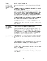
Page 7: ...KEN WIRE With speed control knob at 100 dial setting check DC voltage between field terminals marked F and F on SCR control and between terminals 3 and 5 on terminal strip in control box voltage should be 200 VDC check DC voltage between armature terminals marked A and A on SCR control and between terminals 4 and 6 on terminal strip in control box voltage should be 180 VDC 4 BLOWN FUSE In the prev...

Page 8: ...A and A on SCR control Turn speed control knob CW needle on voltmeter should increase and be at 180 VDC when speed control knob reaches 100 dial setting If voltmeter does not increase at a rate in relation to the turning of the speed control knob the potentiometer may be faulty and the SCR control will need to be replaced In some cases just the potentiometer can be replaced if it is separate from ...

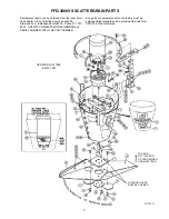
Page 9: ...7 787 6341 SPECIFY COMPLETE MODEL NUMBER and SERIAL NUMBER WITH THE PART NUMBER Any parts or equipment sent to the factory must be shipped freight prepaid and be accompanied with form RMF 03 5 fully completed FFD 3000VS SCATTERGRAIN PARTS LOCATING HOLES MUST BE ALIGNED TOP END TILT THIS END UP FOR DESIRED GRAIN PATTERN UPDATED JAN 1988 MAY 1997 ...

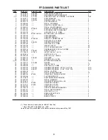
Page 10: ...1 24 311 1024 0 A11 015 U BOLT 3 8 16 x 1 x 2 1 4 2 25 090 1140 4 SKCP 5 16 18 x 1 4 2 26 093 1003 8 ROLL PIN 1 4 x 1 BLACK 1 27 308 1021 2 A08 021 GEAR BOX 1 28 420 2012 3 GASKET 6 1 2 x 4 17 32 1 1 30 017 1534 1 MOTOR PINION SLEEVE REF 31 321 1001 7 A21 002 GASKET 1 32 091 1040 4 HEX NUT 3 8 16 10 33 090 1086 9 HHCS 3 8 16 x 1 GR 5 6 34 306 1035 6 A06 012 HANGER EXTENSION UP TO 31 3 4 DIA 3AR 35...

Page 11: ...0 31 Part No 22 018 7 1 2 344 21 37 53 011 53 007 22 022 29 083 420 2019 8 Description Cover gasket Fuse block single Boot Ground lug O ring Decal 8x3 8 pan hd screw B 6x3 8 pan hd screw B 6x1 2 pan hd screw B 6x5 8 pan hd screw B 1 4 20x3 4 hex head screw 1 4 20 hex head nut ESNA Decal warning 1 4 Flat washer X 4 1 1 1 1 1 3 2 2 3 2 2 1 2 FFD 3000VS CONTROL BOX ASSY 1 PH 3 PH 220V 1 2 3 4 5 6 P1 ...

Page 12: ...box mounting brkt Ground lug Double fuse holder Fuse 5A 600V Transformer 1 5KVA Motor control board Knob Terminal strip Terminal strip marker Indicator light 250V red Toggle switch DPST Fuse block spacer Fuse block double Fuse 8A 250V Boot O ring X 1 1 2 2 1 1 1 1 2 1 1 1 1 1 1 1 2 1 2 1 1 Item 22 23 24 25 26 27 28 29 30 31 P N M K J F E D C B A Part No 48 013 3 22 022 53 002 2 420 1136 1 16 002 5...

Reviews: