Assembly - Teleswing
24
SWING AUGER ASSEMBLY
13” Teleswing
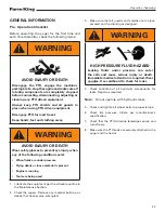
Move the old swing auger into a position out from
the side of the auger that is safe to lift. Secure
an appropriate lifting device with lifting straps or
chains to the swing auger.
Apply slight tension to prevent swing auger from
falling when the fasteners are removed.
Remove fasteners from swivel ring, pivots, and
driveline on old swing unit to disconnect.
Lift off the old swing auger in a safe manner.
Remove old swivel ring and driveline.
Move the old swing auger into a position out from
the side of the auger that is safe to lift.
Secure the new Teleswing auger to an appropriate
lifting device with lifting straps or chains. Move
the Teleswing over the input box to connect.
Grease the Teleswing gearbox spline.
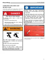
IMPORTANT
Reinstall the old driveline to the Teleswing
auger.
The center of the driveline must be placed in
line with the pivots.
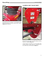
Look through the hole (Item 1)
[Figure 5]
in the
pivot brackets to check that driveline is in line.
Lock driveline in place.
Install the new swivel ring to the input box. Place
accordion pivot cover and two hose clamps around
the swivel ring.
Grease the spline on the input box gearbox.
Lower the Teleswing auger into place. Align pivot
brackets and driveline.
The driveline can be aligned to the spline and
locked through the door on the side of the collector.
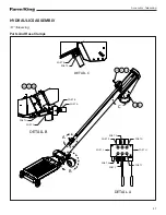
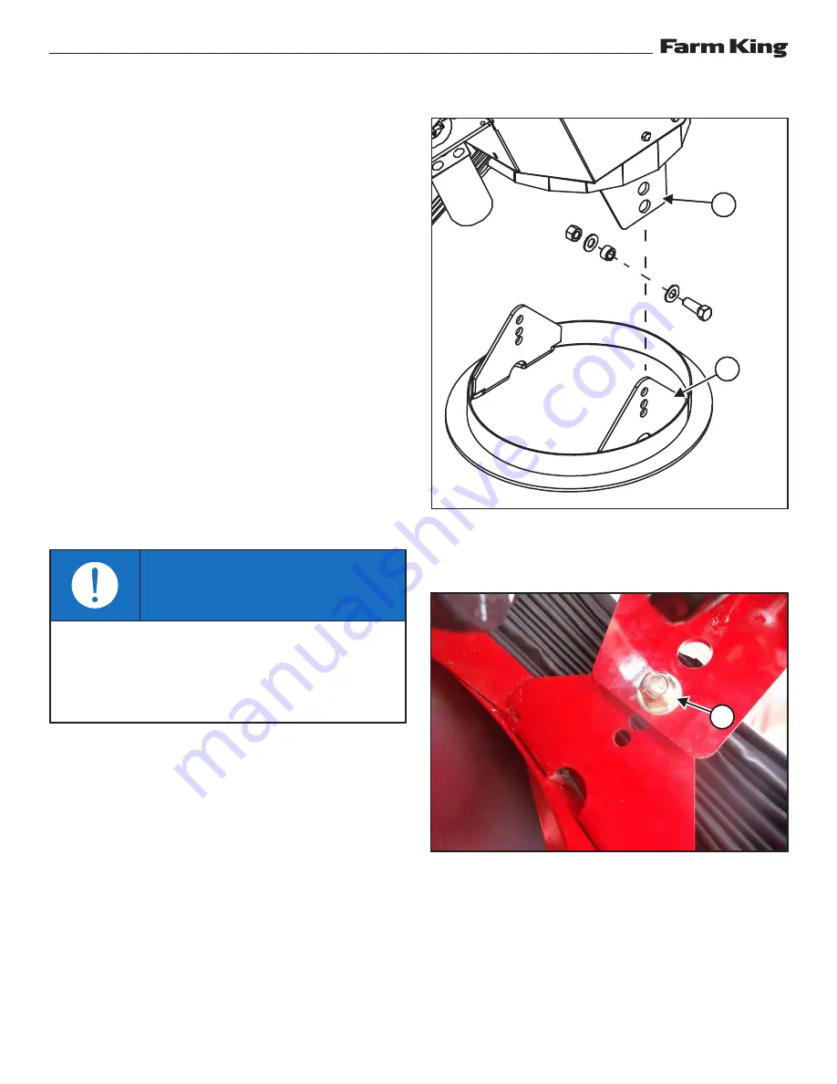
Figure 4
Connect the collector brackets (Item 1) to the
brackets on the swivel ring (Item 2)
[Figure 4]
.
Figure 5
Position top hole of the input box brackets and
bottom hole (Item 1) of the collector brackets
[Figure 5]
.
Attach using 5/8” x 1-3/4” hex bolt, spacer bushing,
5/8” flat washers, and 5/8” lock nut.
1
2
1
Summary of Contents for 13''
Page 1: ...092018 F2426 OPERATOR AND PARTS MANUAL TELESWING AUGER Model 13 16 ...
Page 2: ......
Page 4: ... Teleswing 2 ...
Page 6: ...Warranty Registration Form Teleswing 4 ...
Page 8: ...Introduction Teleswing 6 ...
Page 12: ...Safety Teleswing 10 ...
Page 17: ...Safety Teleswing 15 ...
Page 22: ...Safety Teleswing 20 ...
Page 24: ...Assembly Teleswing 22 ...
Page 32: ...Assembly Teleswing 30 ...
Page 34: ...Operation Teleswing 32 ...
Page 40: ...Operation Teleswing 38 ...
Page 42: ...Maintenance Teleswing 40 ...
Page 48: ...Maintenance Teleswing 46 ...
Page 66: ...Parts Identification Teleswing 64 ROLLER FLANGE 5 2 1 3 4 6 3 7 934701 ...
Page 88: ...Parts Identification Teleswing 86 ...
Page 90: ...Specifications Teleswing 88 ...
Page 96: ...Warranty Teleswing 94 ...
Page 99: ......


